AIR CONDITIONING
2.0L
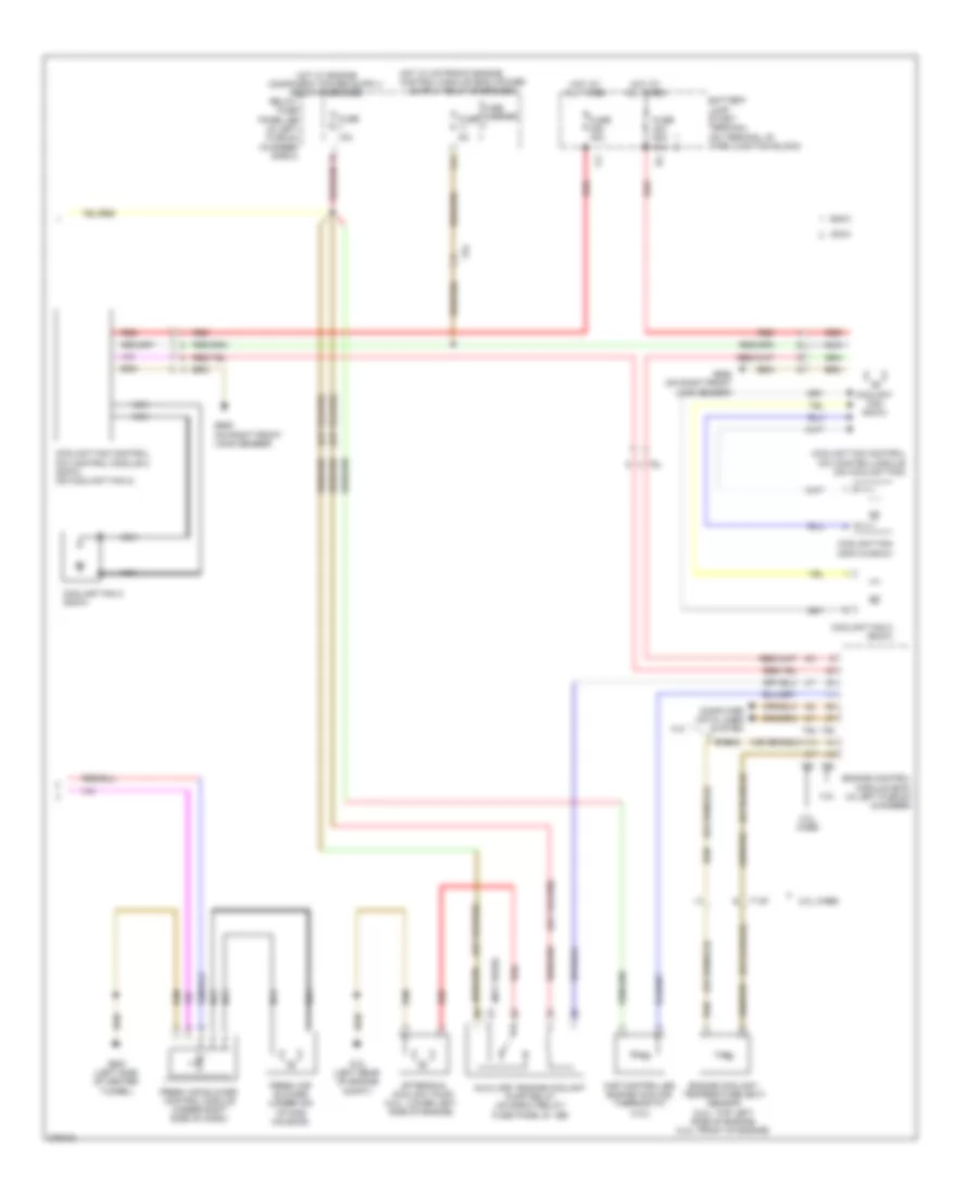
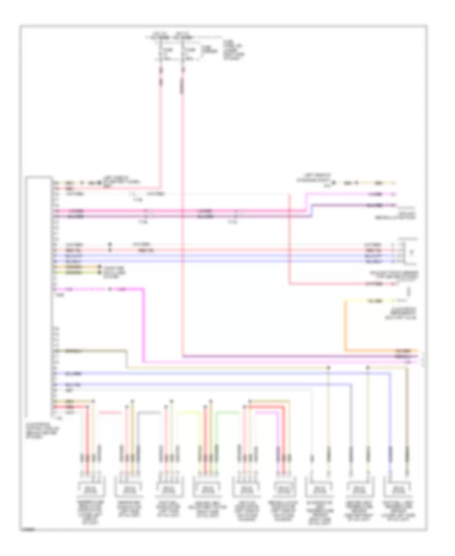
2.0L, Automatic A/C Wiring Diagram, CAEB with Basic (1 of 2) for Audi A5 2.0T Quattro 2012

List of elements for 2.0L, Automatic A/C Wiring Diagram, CAEB with Basic (1 of 2) for Audi A5 2.0T Quattro 2012:
- (behind center of grille)
- (left side of center tunnel) g687
- (top center of dash)
- 10a
- A/c compressor regulator valve (rear of a/c compressor)
- A/c pressure/ temperature sensor (on a/c high pressure line)
- Air flow door motor (left side of air intake housing)
- Center vent adjustment motor (right side of a/c unit)
- Center vent temperature sensor (center front of a/c unit)
- Climatronic control module (behind center of dash)
- Climatronic refrigerant shut-off valve (2.0l caeb)
- Computer data lines system
- Coolant recirculation pump
- Defroster door motor (left side of a/c unit)
- Engine coolant level (ecl) sensor
- Evaporator vent temperature sensor (right side of a/c unit)
- Footwell door motor (left side of a/c unit)
- Footwell vent temperature sensor (lower left side of a/c unit)
- Fuse 10a
- Fuse 40a
- Fuse 5a
- Fuse carrier
- Fuse panel sc (under left side of dash)
- Fuse panel sd (under right side of dash)
- G12
- G639 (behind left kick panel)
- Hot at all times
- Outside air temperature sensor
- Recirculation door motor (left side of air intake housing)
- Red
- Solid state
- Sunlight photo sensor
- T16b
- T16i
- T17b
- T17i
- T17q
- T17r
- T20e
- T32b
- Temperature regulator door motor (lower left side of a/c unit)
- Vehicle electrical system control module (on relay & fuse panel)
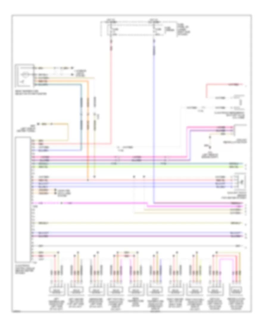
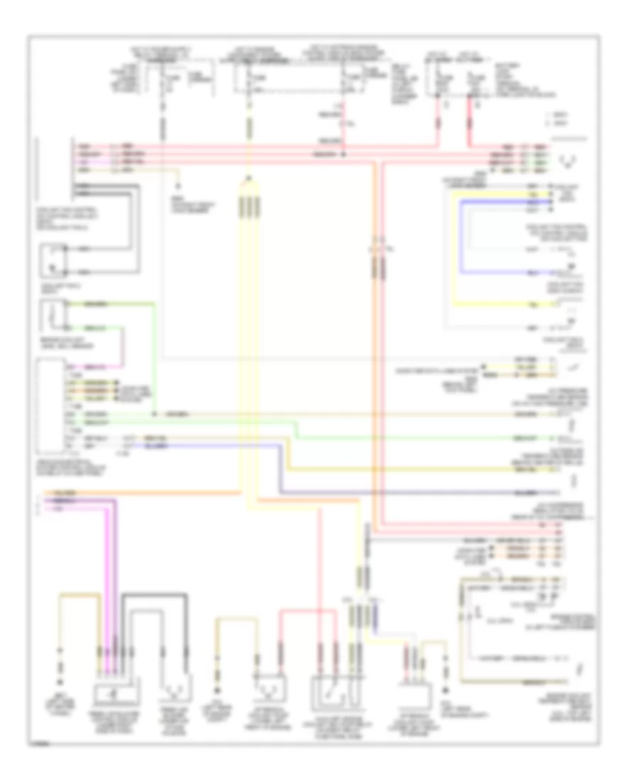
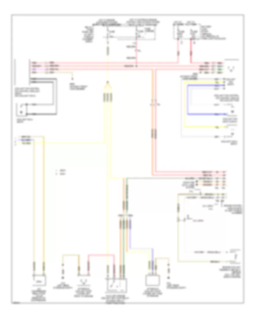
2.0L, Automatic A/C Wiring Diagram, CAEB with Basic (2 of 2) for Audi A5 2.0T Quattro 2012
List of elements for 2.0L, Automatic A/C Wiring Diagram, CAEB with Basic (2 of 2) for Audi A5 2.0T Quattro 2012:
- (not used)
- 11a
- 2.0l caeb
- 4.2l
- 400w
- 600w
- After-run coolant pump (2.0l: lower left side of engine)
- Auxiliary engine coolant pump relay (on e-box relay/ fuse panel b - sb)
- Battery jump start terminal (on terminal 30 wire junction block)
- Computer data lines system
- Coolant fan (400w & 600w)
- Coolant fan (800w)
- Coolant fan 2 (600w)
- Coolant fan 2 (800w)
- Coolant fan control (fc) control module (on coolant fan)
- Coolant fan control (fc) control module 2 (800w) (on coolant fan 2)
- Engine control module (ecm) (in left plenum chamber)
- Engine coolant temperature (ect) sensor (2.0l: top left side of engine) (4.2l: front of engine)
- Fresh air blower (under air intake housing)
- Fresh air blower control module (under right side of dash)
- Fuse 10a
- Fuse 40a
- Fuse 5a
- Fuse 60a 40a
- Fuse carrier
- G12 (left rear of engine compt)
- G685 (on right front long member)
- G687 (left side of center tunnel)
- Hot at all times
- Hot w/ motronic engine
- Map controlled engine cooling thermostat (4.2l)
- Nca
- Red
- Relay/ fuse panel sb (in left plenum chamber e-box)
- T14f
- T5l
- T60
- T94
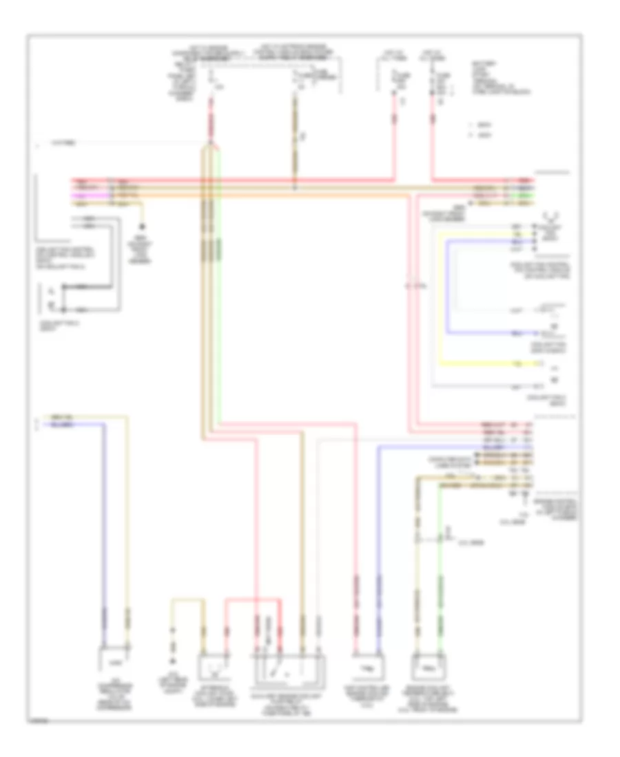
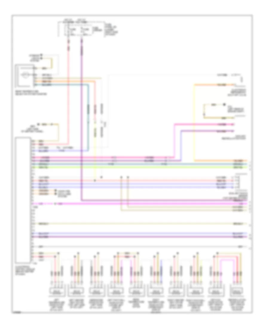
2.0L, Automatic A/C Wiring Diagram, CAEB with Comfort (1 of 3) for Audi A5 2.0T Quattro 2012
List of elements for 2.0L, Automatic A/C Wiring Diagram, CAEB with Comfort (1 of 3) for Audi A5 2.0T Quattro 2012:
- 10a
- Air flow door motor (left side of air intake housing)
- Climatronic control module (behind center of dash)
- Climatronic refrigerant shut-off valve (2.0l caeb)
- Computer data lines system
- Coolant recirculation pump
- Defroster door motor (left side of a/c unit)
- Fuse 10a
- Fuse 40a
- Fuse carrier
- Fuse panel sd (under right side of dash)
- G12 (left rear of engine compt)
- G687 (left side of center tunnel)
- Hot at all times
- Interior lights system
- Left center vent motor (top left side of a/c unit)
- Left footwell door motor (lower left side of a/c unit)
- Left temperature door motor (left side of a/c unit)
- Rear temperature door motor
- Rear temperature selection potentiometer
- Recirculation door motor (left side of air intake housing)
- Red
- Right center vent motor (right side of a/c unit)
- Right footwell door motor (lower right side of a/c unit)
- Right temperature door motor (upper right side of a/c unit)
- Solid state
- Sunlight photo sensor (top center of dash)
- T16i
- T17b
- T17d
- T17q
- T20e
2.0L, Automatic A/C Wiring Diagram, CAEB with Comfort (2 of 3) for Audi A5 2.0T Quattro 2012
List of elements for 2.0L, Automatic A/C Wiring Diagram, CAEB with Comfort (2 of 3) for Audi A5 2.0T Quattro 2012:
- (behind center of grille) outside air temperature sensor
- (right rear of enigne compt, in fresh air intake) air quality sensor
- A/c pressure/ temperature sensor (on a/c high pressure line)
- Automatic day/ night interior mirror
- Computer data lines system
- Engine coolant level sensor
- Evaporator vent temperature sensor (right side of a/c unit)
- Fresh air blower (under air intake housing)
- Fresh air blower control module (under right side of dash)
- Fuse 5a
- Fuse carrier
- Fuse panel sc (under left side of dash)
- G639 (behind left kick panel)
- G687 (left side of center tunnel)
- Humidity & rain/light recognition sensor
- Left footwell vent temperature sensor (left side of a/c unit)
- Left front upper body vent temperature sensor
- Nca
- Right footwell vent temperature sensor (lower right side of a/c unit)
- Right front upper body vent temperature sensor (behind right side of dash)
- T16b
- T17i
- T17r
- T32b
- T3c
- Vehicle electrical system control module (on relay & fuse panel)
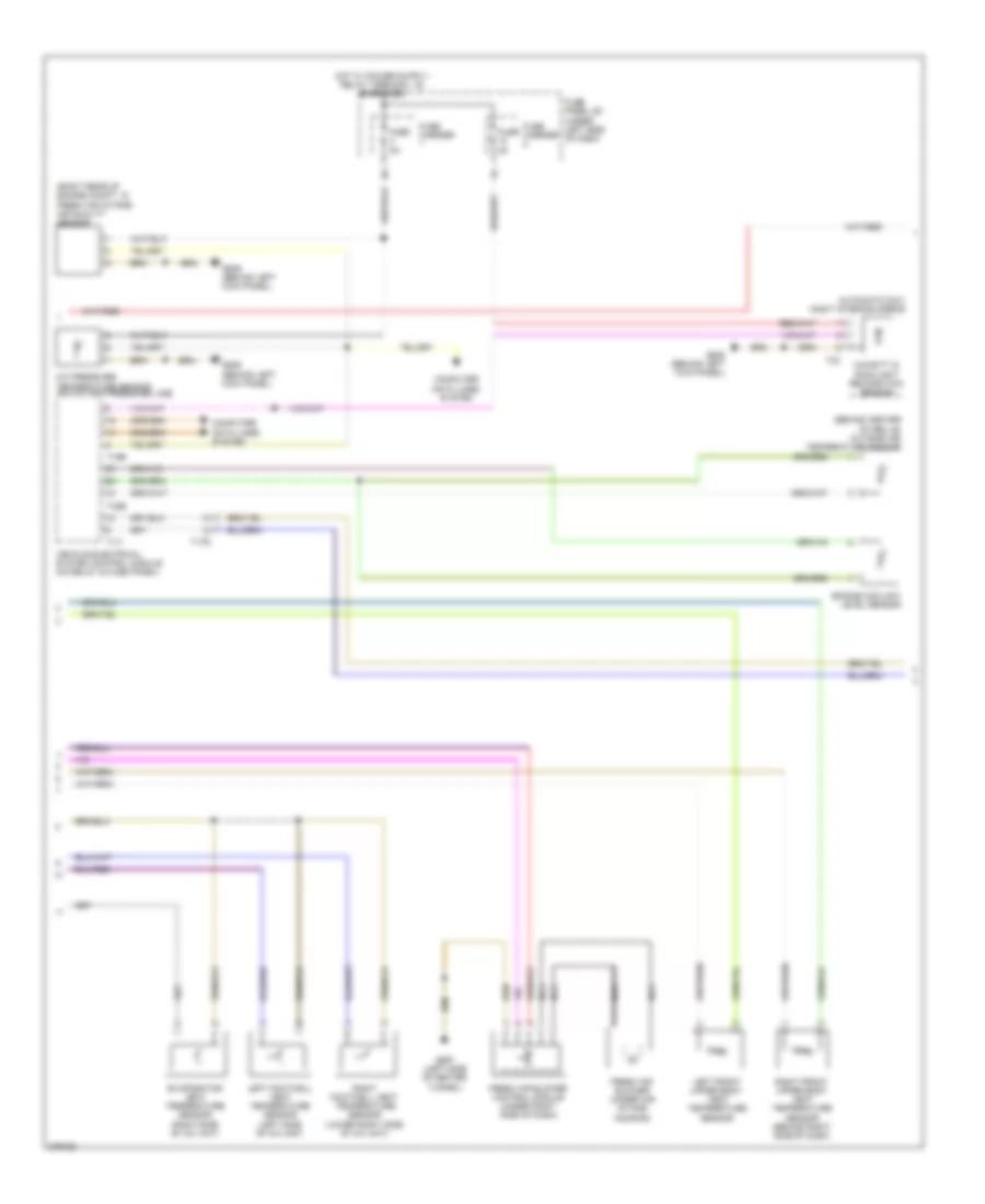
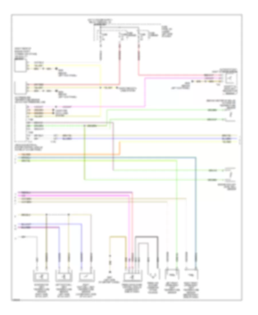
2.0L, Automatic A/C Wiring Diagram, CAEB with Comfort (3 of 3) for Audi A5 2.0T Quattro 2012
List of elements for 2.0L, Automatic A/C Wiring Diagram, CAEB with Comfort (3 of 3) for Audi A5 2.0T Quattro 2012:
- (not used)
- 10a
- 11a
- 2.0l ceab
- 4.2l
- 400w
- 600w
- A/c compressor regulator valve (rear of a/c compressor)
- After-run coolant pump (2.0l: lower left side of engine)
- Auxiliary engine coolant pump relay (on e-box relay/ fuse panel b - sb)
- Battery jump start terminal (on terminal 30 wire junction block)
- Computer data lines system
- Coolant fan (400w & 600w)
- Coolant fan (800w)
- Coolant fan 2 (600w)
- Coolant fan 2 (800w)
- Coolant fan control (fc) control module (on coolant fan)
- Coolant fan control (fc) control module 2 (800w) (on coolant fan 2)
- Engine control module (ecm) (in left plenum chamber)
- Engine coolant temperature (ect) (2.0l: top left side of engine) (4.2l: front of engine)
- Fuse 40a
- Fuse 5a
- Fuse 60a 40a
- Fuse carrier
- G12 (left rear of engine compt)
- G685 (on right front long member)
- Hot at all times
- Hot w/ engine
- Map controlled engine cooling thermostat (4.2l)
- Nca
- Red
- Relay energized
- Relay/ fuse panel sb (in left plenum chamber e-box)
- T14f
- T5l
- T60
- T94
2.0L, Automatic A/C Wiring Diagram, CPMA with Basic (1 of 2) for Audi A5 2.0T Quattro 2012
List of elements for 2.0L, Automatic A/C Wiring Diagram, CPMA with Basic (1 of 2) for Audi A5 2.0T Quattro 2012:
- (left rear of
- (left side of of center tunnel) g687
- 10a
- Air flow door motor (left side of air intake housing)
- Center vent adjustment motor (right side of a/c unit)
- Center vent temperature sensor (center front of a/c unit)
- Climatronic control module (behind center of dash)
- Climatronic refrigerant shut-off valve
- Computer data lines system
- Coolant recirculation pump
- Defroster door motor (left side of a/c unit)
- Evaporator vent temperature sensor (right side of a/c unit)
- Footwell door motor (left side of a/c unit)
- Footwell vent temperature sensor (lower left side of a/c unit)
- Fuse 10a
- Fuse 40a
- Fuse carrier
- Fuse panel sd (under right side of dash)
- G12
- Hot at all times
- Of engine compt)
- Recirculation door motor (left side of air intake housing)
- Red
- Solid state
- Sunlight photo sensor (top center of dash)
- T16i
- T17b
- T17q
- T20e
- Temperature regulator door motor (lower left side of a/c unit)
2.0L, Automatic A/C Wiring Diagram, CPMA with Basic (2 of 2) for Audi A5 2.0T Quattro 2012
List of elements for 2.0L, Automatic A/C Wiring Diagram, CPMA with Basic (2 of 2) for Audi A5 2.0T Quattro 2012:
- (behind center of grille)
- (on a/c high pressure line)
- 11a
- 12a
- 2.0l
- 2.0l cpma
- 2.0l cpma 3.0l
- 3.0l
- 400w
- 600w
- A/c compressor regulator valve (rear of a/c compressor)
- A/c pressure/ temperature sensor
- After-run coolant pump (lower left front of engine)
- Auxiliary engine coolant (ec) pump relay (on e-box relay/ fuse panel b-sb)
- Battery jump start terminal (on terminal 30 wire junction block)
- Computer data lines system
- Coolant fan (400w & 600w)
- Coolant fan (800w)
- Coolant fan 2 (600w)
- Coolant fan 2 (800w)
- Coolant fan control (fc) control module (on coolant fan)
- Coolant fan control (fc) control module 2 (800w) (on coolant fan 2)
- Engine control module (ecm) (in left plenum chamber)
- Engine coolant level (ecl) sensor
- Engine coolant temperature (ect) sensor (2.0l: top left side of engine)
- Fresh air blower (under air intake housing)
- Fresh air blower control module (under right side of dash)
- Fuse 15a
- Fuse 40a
- Fuse 5a
- Fuse 60a 40a
- Fuse carrier
- Fuse panel sc (under left side of dash)
- G12 (left rear of engine compt)
- G639 (behind left kick panel)
- G685 (on right front long member)
- G687 (left side of center tunnel)
- Hot at all times
- Nca
- Outside air temperature sensor
- Red
- Relay/ fuse panel sb (in left plenum chamber e-box)
- T14f
- T16b
- T17i
- T17r
- T32b
- T5l
- T60
- T94
- Vehicle electrical system control module (on relay & fuse panel)
2.0L, Automatic A/C Wiring Diagram, CPMA with Comfort (1 of 3) for Audi A5 2.0T Quattro 2012
List of elements for 2.0L, Automatic A/C Wiring Diagram, CPMA with Comfort (1 of 3) for Audi A5 2.0T Quattro 2012:
- 10a
- Air flow door motor (left side of air intake housing)
- Climatronic control module (behind center of dash)
- Climatronic refrigerant shut-off valve
- Computer data lines system
- Coolant recirculation pump
- Defroster door motor (left side of a/c unit)
- Fuse 10a
- Fuse 40a
- Fuse carrier
- Fuse panel sd (under right side of dash)
- G12 (left rear of engine compt)
- G687 (left side of center tunnel)
- Hot at all times
- Interior lights system
- Left center vent motor (top left side of a/c unit)
- Left footwell door motor (lower left side of a/c unit)
- Left temperature door motor (left side of a/c unit)
- Rear temperature door motor
- Rear temperature selection potentiometer
- Recirculation door motor (left side of air intake housing)
- Red
- Right center vent motor (right side of a/c unit)
- Right footwell door motor (lower right side of a/c unit)
- Right temperature door motor (upper right side of a/c unit)
- Solid state
- Sunlight photo sensor (top center of dash)
- T16i
- T17b
- T17d
- T17q
- T20e
2.0L, Automatic A/C Wiring Diagram, CPMA with Comfort (2 of 3) for Audi A5 2.0T Quattro 2012
List of elements for 2.0L, Automatic A/C Wiring Diagram, CPMA with Comfort (2 of 3) for Audi A5 2.0T Quattro 2012:
- (behind center of grille) outside air temperature sensor
- (behind left kick panel)
- (right rear of
- 12a
- A/c pressure/ temperature sensor (on a/c high pressure line)
- Air quality sensor
- Automatic day/ night interior mirror
- Computer data lines system
- Engine compt,
- Engine coolant level (ecl) sensor
- Evaporator vent temperature sensor (right side of a/c unit)
- Fresh air blower (under air intake housing)
- Fresh air blower control module (under right side of dash)
- Fuse 5a
- Fuse carrier
- Fuse panel sc (under left side of dash)
- G639
- G639 (behind left kick panel)
- G687 (left side of center tunnel)
- Humidity & rain/light recognition sensor
- In fresh air intake)
- Left footwell vent temperature sensor (left side of a/c unit)
- Left front upper body vent temperature sensor
- Nca
- Right footwell vent temperature sensor (lower right side of a/c unit)
- Right front upper body vent temperature sensor (behind right side of dash)
- T16b
- T17i
- T17r
- T32b
- T3c
- Vehicle electrical system control module (on relay & fuse panel)
2.0L, Automatic A/C Wiring Diagram, CPMA with Comfort (3 of 3) for Audi A5 2.0T Quattro 2012
List of elements for 2.0L, Automatic A/C Wiring Diagram, CPMA with Comfort (3 of 3) for Audi A5 2.0T Quattro 2012:
- 11a
- 2.0l
- 2.0l cpma
- 3.0l
- 400w
- 600w
- A/c compressor regulator valve (rear of a/c compressor)
- After-run coolant pump (lower left front of engine)
- After-run coolant pump (lower left side of engine)
- Auxiliary engine coolant (ec) pump relay (on e-box relay/ fuse panel b-sb)
- Battery jump start terminal (on terminal 30 wire junction block)
- Computer data lines system
- Coolant fan (400w & 600w)
- Coolant fan (800w)
- Coolant fan 2 (600w)
- Coolant fan 2 (800w)
- Coolant fan control (fc) control module (on coolant fan)
- Coolant fan control (fc) control module 2 (800w) (on coolant fan 2)
- Engine control module (ecm) (in left plenum chamber)
- Engine coolant temperature (ect) sensor (2.0l: top left side of engine)
- Fuse 15a
- Fuse 40a
- Fuse 5a
- Fuse 60a 40a
- Fuse carrier
- G12 (left rear of engine compt)
- G685 (on right front long member)
- Hot at all times
- Nca
- Red
- Relay/ fuse panel sb (in left plenum chamber e-box)
- T14f
- T5l
- T60
- T94