AIR CONDITIONING
Automatic A/C Wiring Diagram (1 of 4) for Audi A6 2009

List of elements for Automatic A/C Wiring Diagram (1 of 4) for Audi A6 2009:
- (in center plenum) heat regulating valve & coolant pump
- (right side of hvac assembly) air quality sensor
- A/c compressor regulator valve
- A/c pressure/ temperature sensor
- Center vent motor & position sensor (integral to center vent adjustment motor)
- Climatronic control module
- Computer data lines system
- Front cold air flap motor & position sensor (integral to front cold air flap motor)
- G44 (behind left kick panel)
- G607 (in left plenum chamber)
- G645 (left side of firewall)
- Indirect ventilation flap motor & position sensor (left side of hvac assembly)
- Left footwell flap motor & position sensor (integral to left footwell flap motor)
- Right footwell flap motor & position sensor (integral to right footwell flap motor)
- Right front upper body outlet position sensor (integral to right front upper body outlet motor)
- Seats system (heated seats circuit)
- T16d
- T20f
Automatic A/C Wiring Diagram (2 of 4) for Audi A6 2009
List of elements for Automatic A/C Wiring Diagram (2 of 4) for Audi A6 2009:
- (behind left kick panel) g44
- 41a
- Defroster flap motor & position sensor (integral to defroster flap motor)
- Evaporator vent temperature sensor (right side of hvac assembly)
- Fresh air blower
- Fresh air blower control module
- Fuse 10a
- Fuse 30a
- Fuse 40a
- Fuse 5a
- Fuse panel b
- Fuse panel c
- G607 (in left plenum chamber)
- Hot at all times
- Left front upper body outlet position sensor (integral to left front upper body outlet motor)
- Left vent temperature sensor (upper left side of hvac assembly)
- Nca
- Rear footwell vent motor & position sensor (lower right side of hvac assembly)
- Red
- Right front seat temperature sensor (w/ heated seats)
- Right vent temperature sensor (right side of hvac assembly)
- Solar cells
- Solar operation control module
- Sunroof frame sliding contacts
- W/ heated seats
Automatic A/C Wiring Diagram (3 of 4) for Audi A6 2009
List of elements for Automatic A/C Wiring Diagram (3 of 4) for Audi A6 2009:
- (behind center of dash) g45
- Back pressure flap motor & position sensor
- Center air outlet sensor
- Climatronic control module
- Fresh air intake duct temperature sensor
- G45 (behind center of dash)
- Interior lights system
- Left front seat temperature sensor (w/ heated seats)
- Nca
- Rear window shade switch
- Recirculation flap motor & position sensor
- Red
- Sunlight photo sensor
- T12a
- T16e
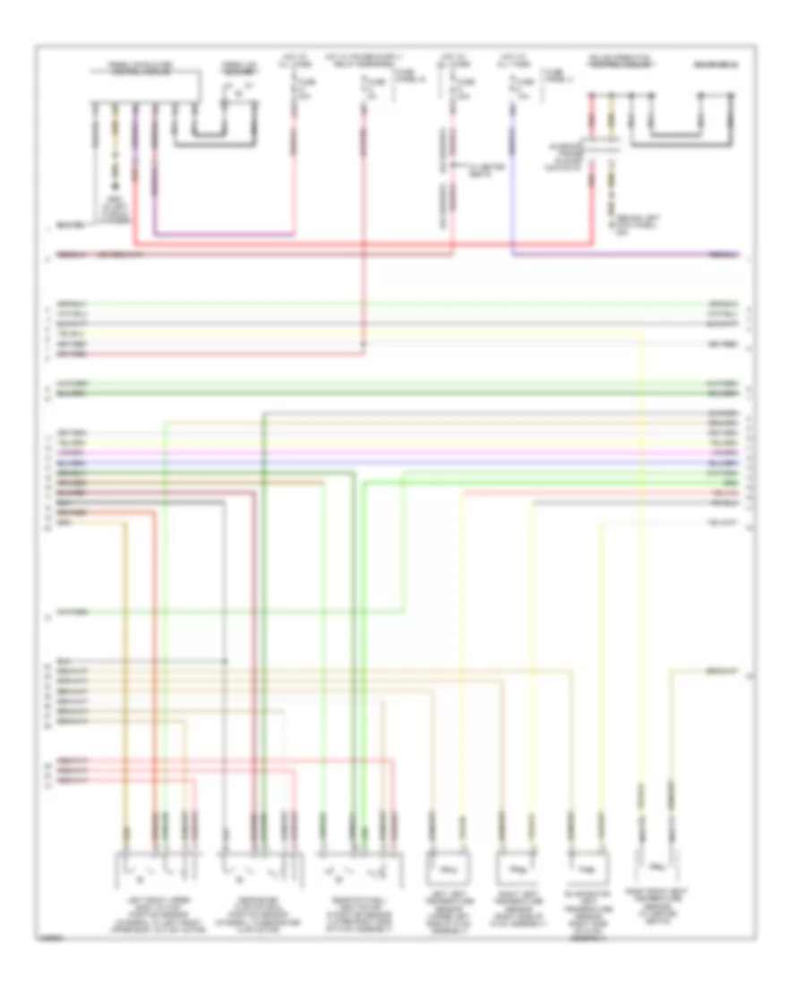
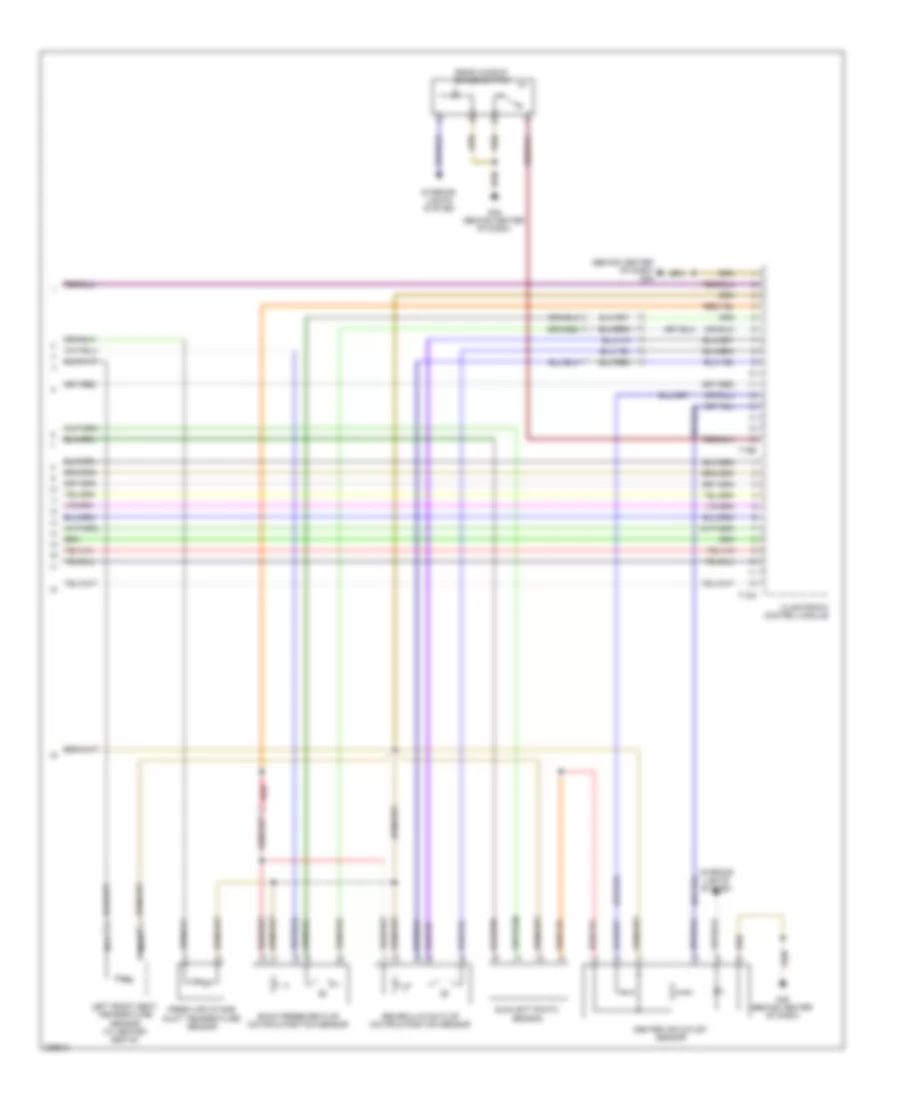
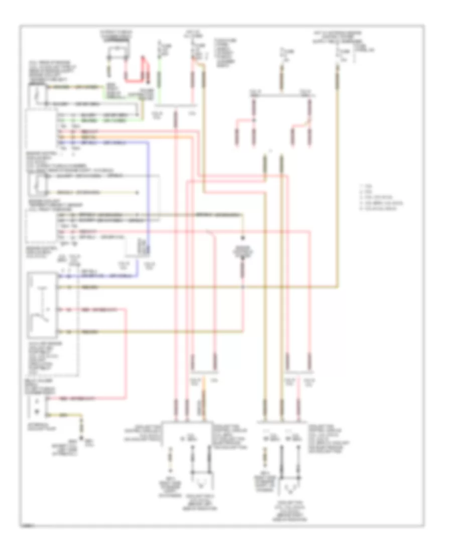
Automatic A/C Wiring Diagram (4 of 4) for Audi A6 2009
List of elements for Automatic A/C Wiring Diagram (4 of 4) for Audi A6 2009:
- (5.2l: rear of engine) (4.2l: in coolant pipe at rear of engine compt) engine coolant temperature (ect) sensor
- (in right plenum chamber e-box) suppressor
- 3.0l & 3.2l (cala)
- 3.2l
- 3.2l & 3.0l
- 3.2l (bkh)
- 3.2l (bkh), 4.2l & 5.2l
- 3.2l, 3.0l & 4.2l
- 4.2l
- 4.2l & 5.2l
- 5.2l
- After-run coolant pump
- Auxiliary engine coolant (ec) pump relay (3.2l, 5.2l & 3.0l) coolant circulation pump relay (4.2l)
- Coolant fan (3.0l, 3.2l (cala), 4.2l & 5.2l) (behind right side of radiator)
- Coolant fan 2 (4.2l & 5.2l) (behind left side of radiator)
- Coolant fan control module (3.0l, 3.2l (cala), 4.2l, 5.2l & 3.2l (bkh) w/ coolant fan electronics) (on coolant fan)
- Coolant fan control module (3.2l (bkh) w/ coolant fan electronics) (on coolant fan)
- Coolant fan control module 2 (4.2l & 5.2l) (on coolant fan 2)
- Engine control module (ecm) (3.2l & 3.0l)
- Engine control module (ecm) (4.2l & 5.2l) (4.2l: in right plenum chamber) (5.2l: right rear of engine compt, in plenum)
- Engine controls system
- Engine coolant temperature (ect) sensor (3.2l: front of engine)
- Fuse 10a
- Fuse 5a
- Fuse 60a
- Fuse 60a 40a
- Fuse panel sa
- G601 (3.0l)
- G614 (right side of engine compt, on chassis)
- G645 (except 3.0l) (left side of firewall)
- G646 (right side of firewall)
- Hot at all times
- Main fuse panel (e-box) (in right plenum chamber e-box)
- Nca
- Power distribution system
- Red
- Relay holder (e-box) (in left plenum chamber e-box)
- T60
- T60a
- T94
- T94a