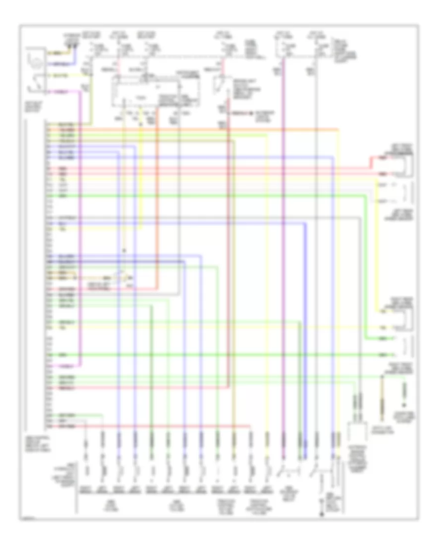
ANTI-LOCK BRAKES
Anti-lock Brakes Wiring Diagram, AWD for Audi A8 1999

List of elements for Anti-lock Brakes Wiring Diagram, AWD for Audi A8 1999:
- (above left kick panel) g44
- 10a
- Abs control module (below left side of dash)
- Abs inlet valves
- Abs outlet valves
- Abs return flow pump relay
- Abs solenoid valve relay
- Abs warning light
- Brakelight switch (above brake pedal, on bracket)
- C24
- Computer data lines system
- Data link connector
- Exterior lights system
- Fuse 1 (st3) 15a
- Fuse 10 (st4) 10a
- Fuse 4 (st3) 10a
- Fuse 50a
- Fuse 9 (st2) 10a
- Fuse panel (right front footwell)
- G44 (above
- Hot at all times
- Hot in on or start
- Instrument cluster
- Left front
- Left front abs wheel speed sensor
- Left kick panel)
- Left rear
- Left rear abs wheel speed sensor
- Motronic engine control module (in plenum chamber e-box)
- Red
- Relay & fuse panel (right side of luggage compt)
- Right front
- Right front abs wheel speed sensor
- Right rear
- Right rear abs wheel speed sensor
- T26
- T26a
- Tf6
- Traction control outlet valves
- Traction control switch- over valves
Anti-lock Brakes Wiring Diagram, FWD for Audi A8 1999
List of elements for Anti-lock Brakes Wiring Diagram, FWD for Audi A8 1999:
- (above left kick panel)
- 10a
- A12
- Abs control module (below left side of dash)
- Abs hydraulic unit (left front of engine compt)
- Abs inlet valves
- Abs outlet valves
- Abs return flow relay & pump
- Abs solenoid valve relay
- Abs warning light
- Anti-slip control switch
- Brakelight switch (above brake pedal, on bracket)
- C24
- Chamber e-box)
- Computer data lines system
- Data link connector
- Exterior lights system
- Fuse 1 (st3) 15a
- Fuse 10 (st4) 10a
- Fuse 25a
- Fuse 4 (st3) 10a
- Fuse 50a
- Fuse 9 (st2) 10a
- Fuse panel (right front footwell)
- G44
- Hot at all times
- Hot in on or start
- Instrument cluster
- Interior lights system
- Left front
- Left front abs wheel speed sensor
- Left rear
- Left rear abs wheel speed sensor
- Motronic engine control module (in plenum
- Red
- Relay & fuse panel (right side of luggage compt)
- Right front
- Right front abs wheel speed sensor
- Right rear
- Right rear abs wheel speed sensor
- T26
- T26a
- Tach
- Tf6
- Traction control indicator
- Traction control outlet valves
- Traction control switch-over valves