ANTI-LOCK BRAKES
Anti-lock Brakes Wiring Diagram for Audi S8 Quattro 2009
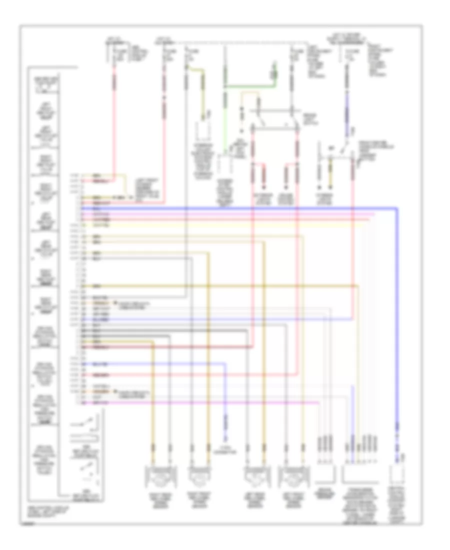
List of elements for Anti-lock Brakes Wiring Diagram for Audi S8 Quattro 2009:
- (left front chassis member, forward of front axle) g12
- 17-pin connector
- 22a
- 27a
- Abs control module (w/edl: left side of engine compt)
- Abs control module fuse 1
- Abs return flow pump
- Abs return flow pump relay
- Abs return flow pump relay 2
- Access/ start control module (under
- Brake light switch
- Brake pressure sender
- Central control module (comfort system) (right side of luggage compt)
- Computer data lines system
- Cruise control system
- Driver's seat)
- Driving dynamics regulation high pressure switch valve 1
- Driving dynamics regulation high pressure switch valve 2
- Driving dynamics regulation switch valve 1
- Driving dynamics regulation switch valve 2
- Exterior lights system
- Front/center console console head (asr/esp button) t16b
- Fuse 25a
- Fuse 5a
- Fuse 60a
- G44 (behind
- Hot at all times
- Interior lights system
- Left front abs inlet valve
- Left front abs outlet valve
- Left front abs wheel speed sensor
- Left instrument panel fuse holder (in left end of dash)
- Left kick panel)
- Left rear abs inlet valve
- Left rear abs outlet valve
- Left rear abs wheel speed sensor
- Right front abs inlet valve
- Right front abs outlet valve
- Right front abs wheel speed sensor
- Right instrument panel fuse holder (in right end of dash)
- Right rear abs inlet valve
- Right rear abs outlet valve
- Right rear abs wheel speed sensor
- Steering column electronic systems control module (top of steering column)
- T16a
- T16b
- T32b
- T6r
- Transverse acceleration sensor/rotation rate sender (rotation rate sender: on front tunnel, under extension of center console)
 English