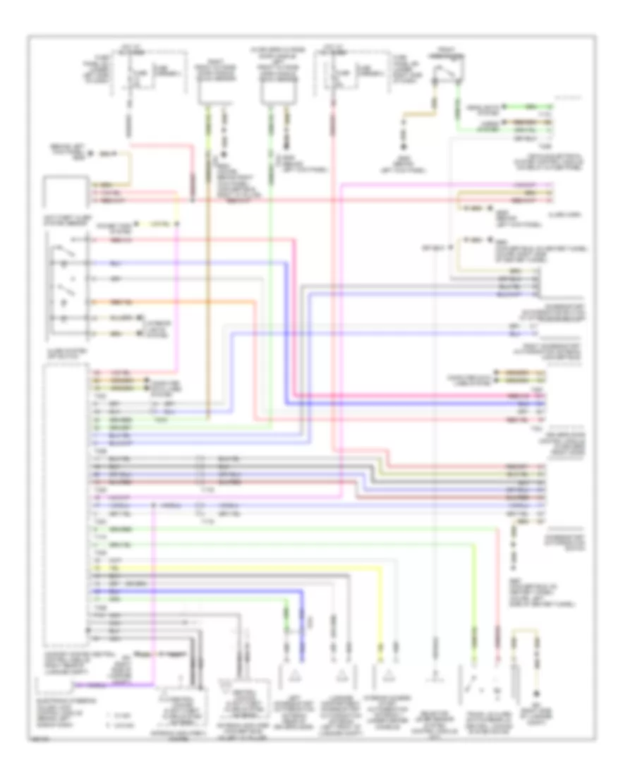
ANTI-THEFT
Anti-theft Wiring Diagram for Audi A5 2.0T Quattro 2011
List of elements for Anti-theft Wiring Diagram for Audi A5 2.0T Quattro 2011:
- (behind left kick panel) g639
- (in driver's outside door handle) left front outside door handle touch sensor
- 12a
- Access/start authorization button (w/ start/stop button)
- Access/start authorization switch
- Alarm horn
- Alarm system off switch
- Antenna amplifier (convertible) (in left "c" pillar)
- Antenna amplifier 3 (coupe)
- Anti-theft alarm system sensor
- Central locking & anti-theft alarm system antenna
- Comfort system central control module (right rear of luggage compt)
- Computer data lines system
- Driver's door control module (in driver's front door)
- Electronic steering column lock control module (behind left side of dash)
- Front hood switch
- Fuse 5a
- Fuse carrier 2
- Fuse carrier 3
- Fuse panel sc (under left side of dash)
- Fuse panel sd (under right side of dash)
- G51 (right side of luggage compt)
- G638 (coupe: behind right kick panel) (convertible: right "a" pillar)
- G639 (behind left kick panel)
- G687 (convertible: on center tunnel) (coupe: left side of center tunnel)
- G688 (convertible: on center tunnel) (coupe: right side of center tunnel)
- Headlights system
- Horns system
- Hot at all times
- Interior access/ start authorization antenna 1 (under center console)
- Interior lights system
- Left access/start authorization antenna (rear of driver's door)
- Luggage compartment access/start authorization antenna (left front of luggage compt)
- Nca
- Power tops system
- Right access/start authorization antenna (convertible)
- Right front outside door handle touch sensor
- Selector lever sensor system control module (a/t)
- T17g
- T17m
- T17o
- T1as
- T1h
- T20f
- T27a
- T27c
- T32b
- T32c
- T32d
- T32e
- T32j
- Trunk lid alarm switch/rear lid central locking system motor
- Vehicle electrical system control module (on relay & fuse panel)
- W/ mmi
- W/o mmi
 English