COMPUTER DATA LINES
Computer Data Lines Wiring Diagram for Audi A6 2001
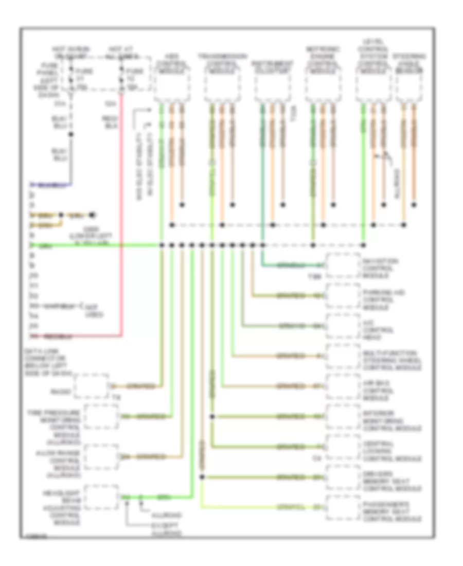
List of elements for Computer Data Lines Wiring Diagram for Audi A6 2001:
- 12a
- 31a
- 4-low range control module (allroad)
- A/c control head
- Abs control module
- Air bag control module
- Allroad
- Central locking control module
- Data link connector (below left side of dash)
- Driver's memory seat control module
- Except allroad
- Fuse 10a
- Fuse 15a
- Fuse panel (left side of dash)
- G900 (lower left "a" pillar)
- Headlight beam adjusting control module
- Hot at all times
- Hot in run or start
- Instrument cluster
- Interior monitoring control module
- Level control system control module
- Motronic engine control module
- Multi-function steering wheel control module
- Navigtion control module
- Not used
- Parking aid control module
- Passenger's memory seat control module
- Radio
- Steering angle sensor
- T32a
- T8m
- Tire pressure monitoring control module (allroad)
- Transmission control module
- W/ elec stability
- W/o elec stability
 English