COOLING FAN
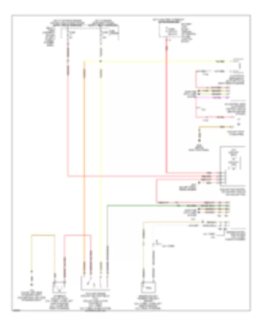
Cooling Fan Wiring Diagram for Audi A5 2.0T Quattro 2010
List of elements for Cooling Fan Wiring Diagram for Audi A5 2.0T Quattro 2010:
- (a/t) coolant fan 2
- (m/t) (a/t)
- (or red)
- 11a
- 2.0l turbo
- 3.2l
- A/c control head climatronic control module (behind center of dash)
- After-run coolant pump (2.0l turbo: lower left side of engine) (3.2l: lower left front of engine)
- Auxiliary engine coolant (ec) pump relay (3.2l) coolant circulation pump relay (2.0l turbo) (2.0l turbo: on relay/fuse carrier e-box-sb)
- Battery jump start terminal (on terminal 30 wire junction block)
- Climatronic refrigerant shut-off valve (right rear of engine)
- Computer data lines system
- Coolant fan
- Coolant fan control (fc) control module (on coolant fan)
- Coolant pump (if equipped)
- Engine control module (ecm) (3.2l: in left plenum chamber)
- Engine coolant temperature (ect) sensor (2.0l turbo: lower left rear of engine) (3.2l: front of engine)
- Fuse 1 40a 60a
- Fuse 15a
- Fuse 5a
- Fuse carrier
- G12 (coupe: left rear of engine compt) (convertible: left side of engine compt)
- G638 (behind right kick panel)
- G671 (on left front cross member)
- Hot w/ battery interrupt igniter energized
- Red
- Relay/ fuse carrier e box sb (in left plenum chamber e-box)
- T14f
- T17b
- T17g
- T17q
- T5i
- T60
- T94
 English