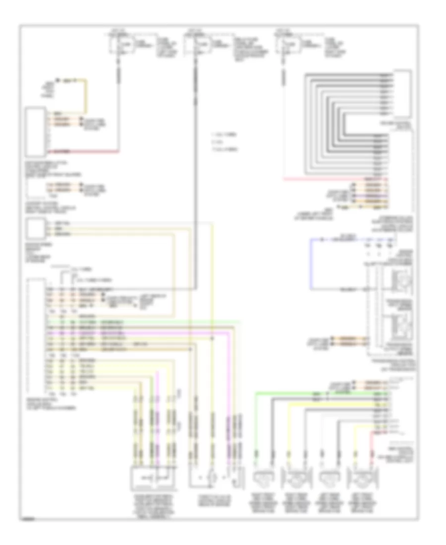
CRUISE CONTROL
Cruise Control Wiring Diagram for Audi Q5 Premium 2013
List of elements for Cruise Control Wiring Diagram for Audi Q5 Premium 2013:
- (left rear of engine compt) g12
- 12a
- 2.0l hybrid
- 2.0l turbo
- 2.0l turbo hybrid
- 3.0l
- Abs control module (on abs hydraulic control unit)
- Accelerator pedal position sensor & accelerator pedal position sensor 2 (top of accelerator pedal assembly)
- Comfort system central control module (right side of trunk)
- Computer data lines system
- Cruise control switch
- Distance regulation control module (if equipped) (right side of front bumper)
- Engine control module (ecm) (in left plenum chamber)
- Engine speed sensor (3.0l) (lower rear of engine)
- Fuse 5a
- Fuse carrier 1
- Fuse carrier 2
- Fuse panel sc (lower left side of dash)
- Fuse panel sd (lower right side of dash)
- G638 (right kick panel)
- G687 (under left front of center console)
- Hot at all times
- Left front abs wheel speed sensor (left front brake hub)
- Left rear abs wheel speed sensor (left rear brake hub)
- Nca
- Red
- Relay/fuse panel sb (driver's side plenum chamber on eletronics box)
- Right front abs wheel speed sensor (right front brake hub)
- Right rear abs wheel speed sensor (right rear brake hub)
- Steering column electronic systems control module (on steering column)
- T105
- T17e
- T17r
- T32c
- T60
- T91
- T94
- Throttle valve control module (rear of engine)
- Transmission control module (tcm) (on transmission)
- Transmission input speed sensor
- Transmission output speed sensor
 English