ENGINE PERFORMANCE
2.0L TURBO
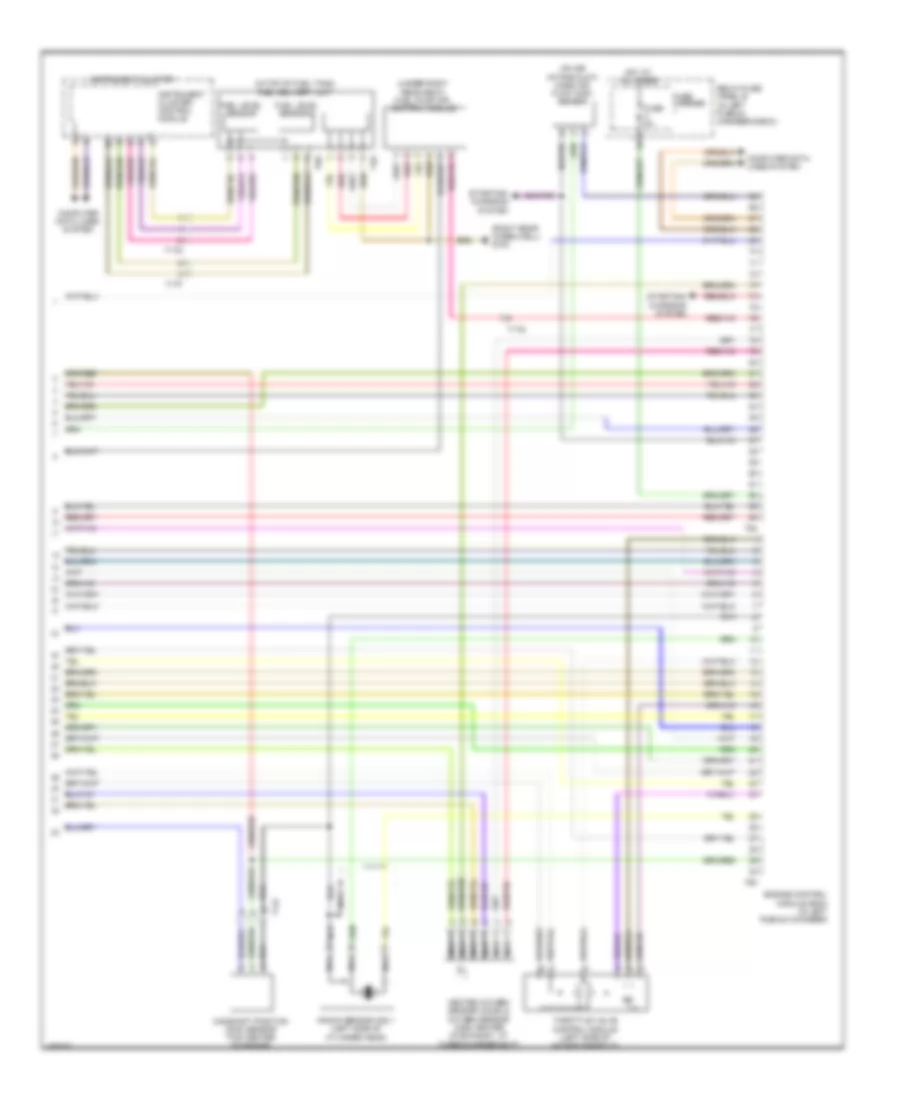
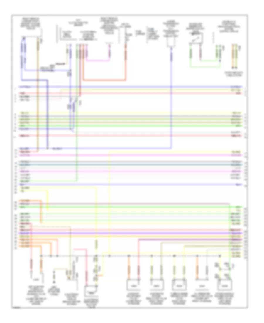
2.0L Turbo, Engine Performance Wiring Diagram, Convertible (1 of 6) for Audi A5 Prestige 2013

List of elements for 2.0L Turbo, Engine Performance Wiring Diagram, Convertible (1 of 6) for Audi A5 Prestige 2013:
- (left side of engine compt) g12
- 14a
- Accelerator pedal position (tp) sensor & accelerator pedal position sensor 2 (top of accelerator pedal assembly)
- Cooling fans system
- Cruise control switch
- Diagnostic pump
- Engine control module (ecm) (in left plenum chamber)
- Exterior lights system
- Fuel tank leak detection control module
- Fuse 10a
- Fuse 15a
- Fuse 20a
- Fuse 5a
- Fuse carrier
- G12 (left side of engine compt)
- M/t
- Nca
- Oil level thermal sensor (bottom of oil pan)
- Oxygen sensor (o2s) behind 3-way catalytic converter & oxygen sensor 1 behind catalytic converter heater (twc) (downstream of catalytic converter)
- Red
- Relay/ fuse panel b (in left plenum chamber e-box)
- Starting/ charging system
- Steering column electronic systems control module (on steering column)
- System
- T16f
- T17b
- T17e
- T17q
- T17r
- T94
- Transmissions
- W/ cruise control
- W/ fuel system
- W/o cruise control
- W/o fuel system
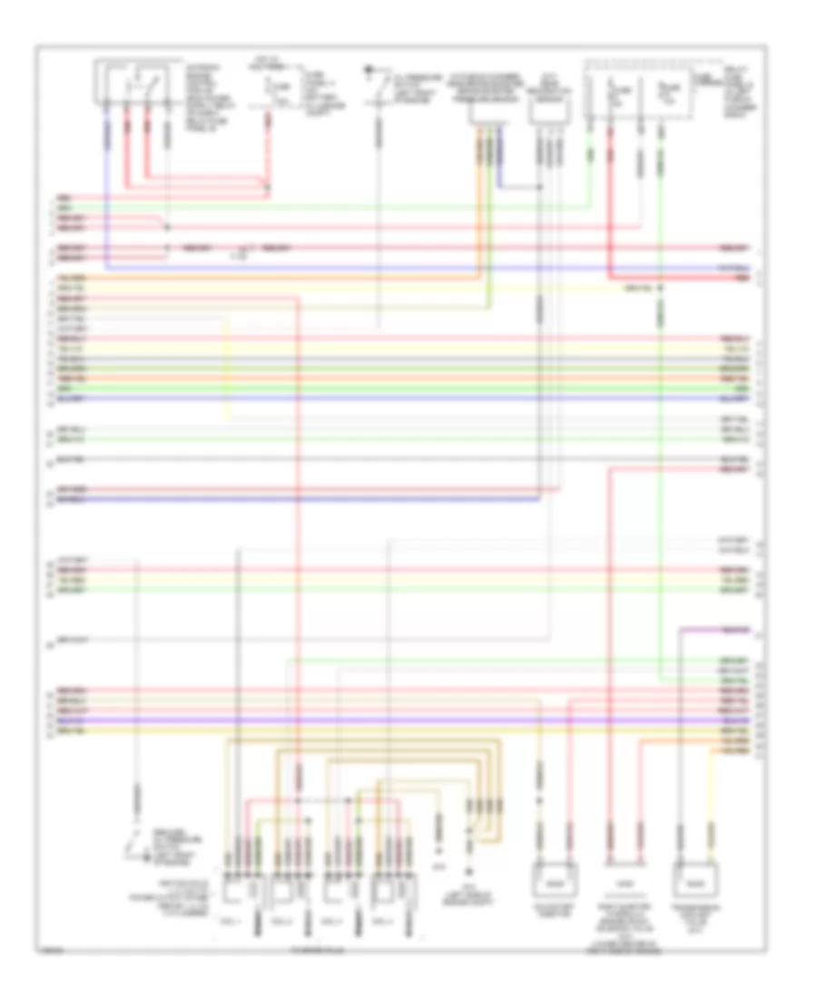
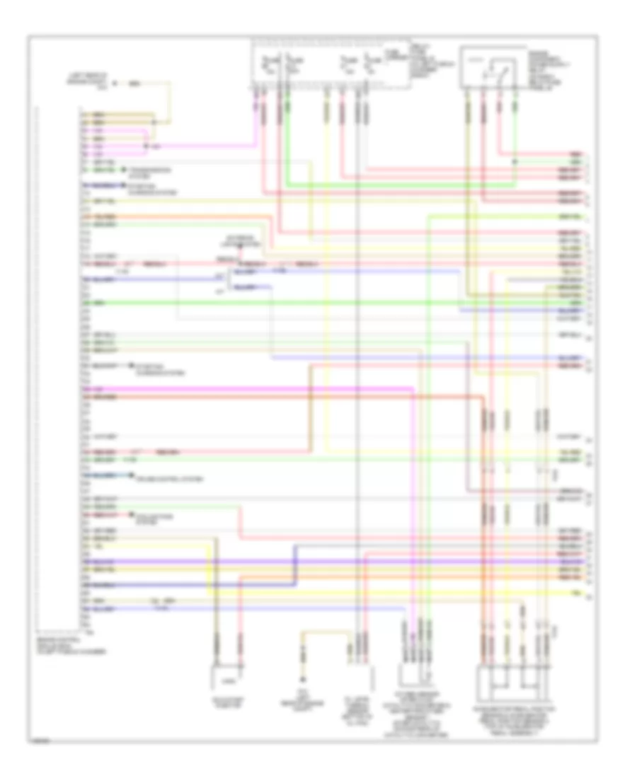
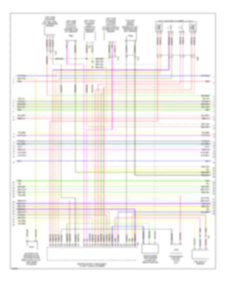
2.0L Turbo, Engine Performance Wiring Diagram, Convertible (2 of 6) for Audi A5 Prestige 2013
List of elements for 2.0L Turbo, Engine Performance Wiring Diagram, Convertible (2 of 6) for Audi A5 Prestige 2013:
- (in plenum chamber, near brake booster) brake booster pressure sensor
- (m/t) gear recognition sensor
- 10a
- Coil 1
- Coil 2
- Coil 3
- Coil 4
- Cold start injector
- Fuse 10a
- Fuse 110a
- Fuse 5a
- Fuse carrier
- Fuse panel a (on battery, in luggage compt)
- G12 (left side of engine compt)
- G18
- Hot at all times
- Ignition coils 1, 2, 3 & 4 w/ power output stage (above 1, 2, 3 & 4 cylinders)
- Nca
- Oil pressure switch (left front of engine)
- Red
- Reduced oil pressure switch (left front of engine)
- Relay/ fuse panel b (in left plenum chamber e-box)
- Right electro hydraulic engine mount solenoid valve (a/t) (lower center of right side of engine)
- T17q
- To spark plug
- Transmission coolant valve (m/t)
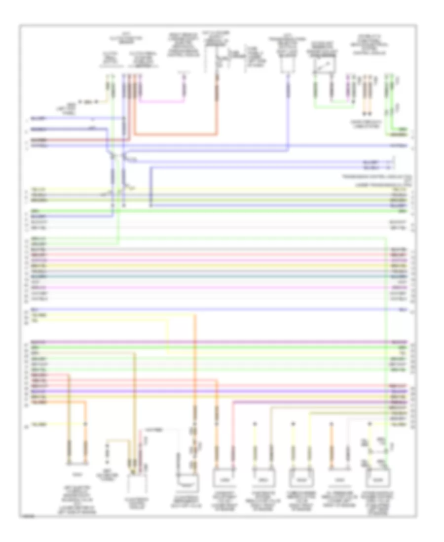
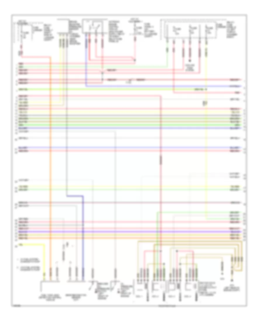
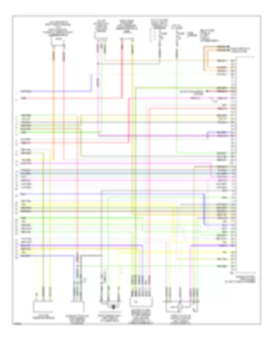
2.0L Turbo, Engine Performance Wiring Diagram, Convertible (3 of 6) for Audi A5 Prestige 2013
List of elements for 2.0L Turbo, Engine Performance Wiring Diagram, Convertible (3 of 6) for Audi A5 Prestige 2013:
- (on brake pedal assembly) brake light switch
- (right rear of engine) fuel pressure regulator valve
- (right rear of luggage compt)
- (top right side of engine)
- 12a
- After-run coolant pump (if equipped) (lower left side of engine)
- Cam adjustment actuator 1
- Cam adjustment actuator 2
- Cam adjustment actuator 3
- Cam adjustment actuator 4
- Cam adjustment actuator 5
- Cam adjustment actuator 6
- Cam adjustment actuator 7
- Cam adjustment actuator 8
- Comfort system central control module
- Fuse 25a
- Fuse 5a
- Fuse carrier
- Fuse panel c (under left side of dash)
- G12 (left side of engine compt)
- Hot at all times
- Red
- Relay/fuse panel f (right side of luggage compt)
- T17e
- T32d
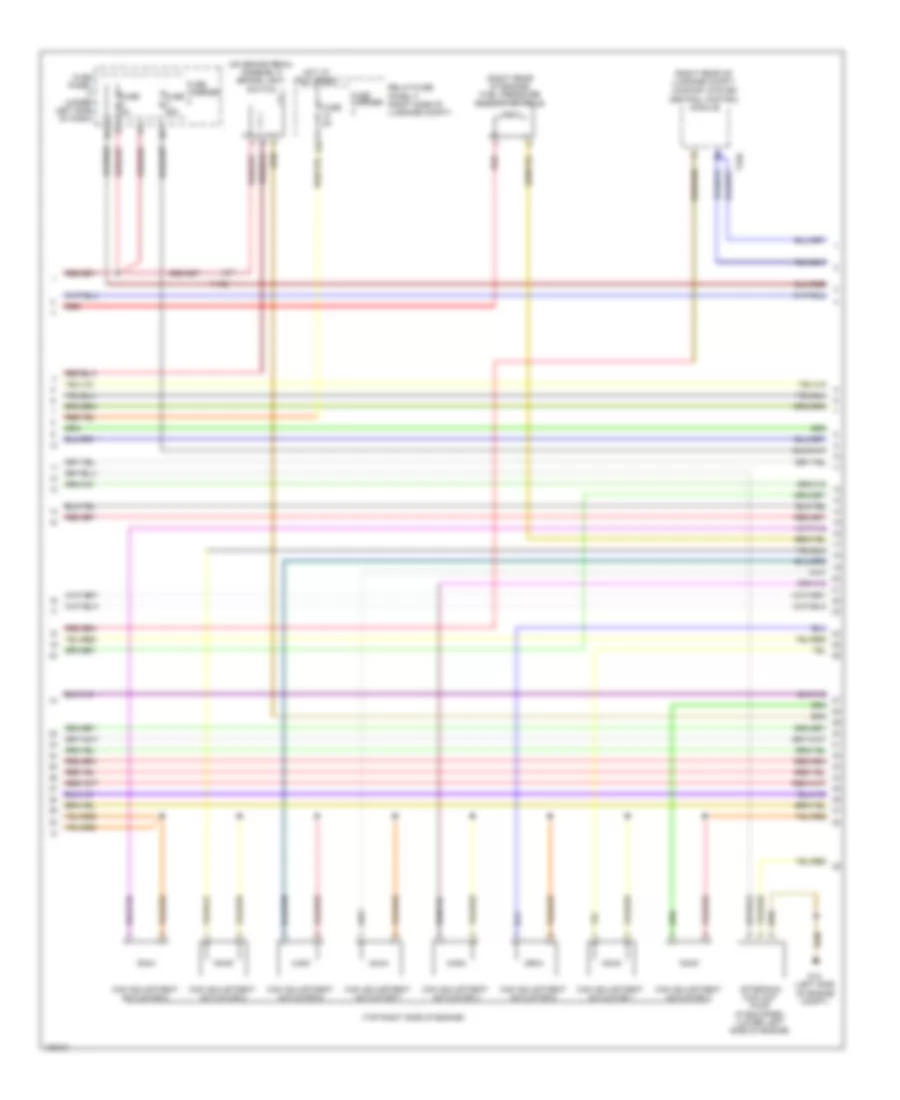
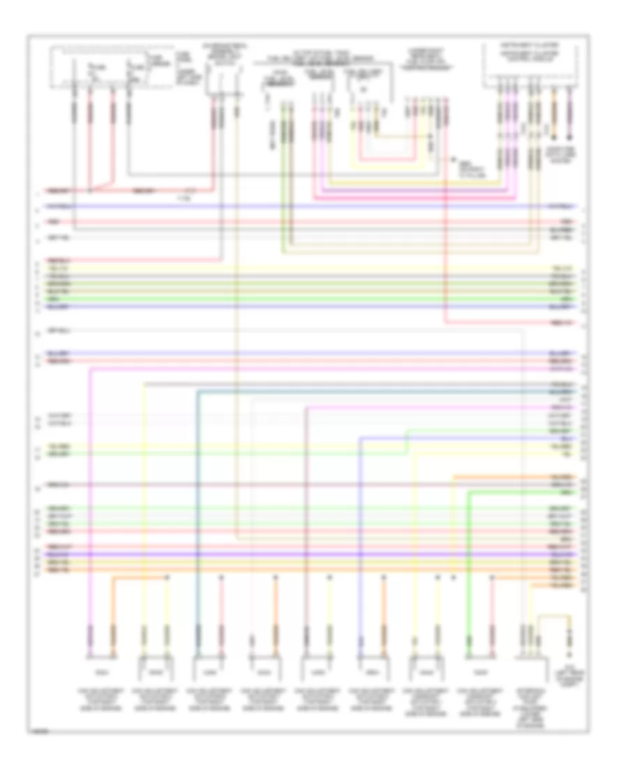
2.0L Turbo, Engine Performance Wiring Diagram, Convertible (4 of 6) for Audi A5 Prestige 2013
List of elements for 2.0L Turbo, Engine Performance Wiring Diagram, Convertible (4 of 6) for Audi A5 Prestige 2013:
- (a/t) transmission park selector switch & shift lock solenoid
- (in coolant reservoir) engine coolant level sensor
- (m/t) clutch position sensor
- (on relay & fuse panel) vehicle electrical system control module
- (right rear of luggage compt) electro mechanical parking brake control module
- 10a
- A/t
- Camshaft adjustment valve 1 (lower front of engine)
- Climatronic control module
- Climatronic refrigerant shut-off valve
- Clutch pedal starter interlock switch
- Clutch pedal switch
- Computer data lines system
- Fuse 5a
- Fuse carrier
- Fuse panel c (under left side of dash)
- G639 (left kick panel)
- G687 (on center tunnel)
- Intake manifold runner control (imrc) valve (if equipped) (left rear of engine)
- Left electro hydraulic engine mount solenoid valve (a/t) (lower center of left side of engine)
- M/t
- Oil pressure regulation valve (lower left front of engine)
- T14f
- T16b
- T17b
- T17l
- T17q
- T20e
- T32b
- Transmission control module (tcm) (a/t) (under transmission oil pan)
- Turbocharger recirculating valve (right front of engine)
- Wastegate bypass regulator valve (right front of engine)
2.0L Turbo, Engine Performance Wiring Diagram, Convertible (5 of 6) for Audi A5 Prestige 2013
List of elements for 2.0L Turbo, Engine Performance Wiring Diagram, Convertible (5 of 6) for Audi A5 Prestige 2013:
- (left front of engine compt) charge air pressure sensor
- (left side of engine, in intake manifold) intake manifold runner position sensor
- (left side of engine, on fuel line) fuel pressure sensor
- (left side of intake manifold) intake air temperature (iat) sensor
- (lower rear of left side of engine) servotronic solenoid valve
- (top left side of engine) engine coolant temperature (ect) sensor
- Engine control module (ecm) (in left plenum chamber)
- Engine speed (rpm) sensor (lower left rear of engine)
- Evaporative emissions (evap) canister purge regulator valve (left rear of engine)
- Fuel injector cylinders 1, 2, 3 & 4
- Low fuel pressure sensor
- T14f
- T60
- T8w
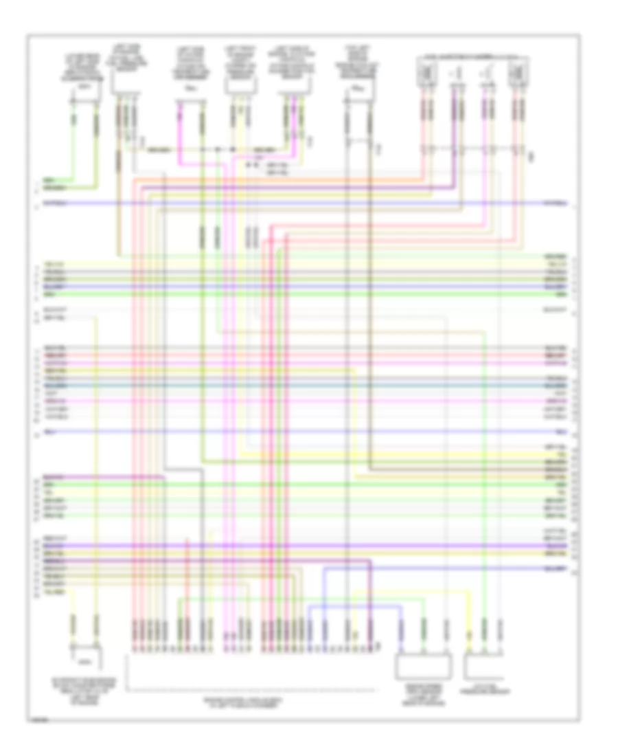
2.0L Turbo, Engine Performance Wiring Diagram, Convertible (6 of 6) for Audi A5 Prestige 2013
List of elements for 2.0L Turbo, Engine Performance Wiring Diagram, Convertible (6 of 6) for Audi A5 Prestige 2013:
- (in top of fuel tank) fuel delivery unit
- (on air intake duct) mass air flow (maf) sensor
- (right rear wheelwell) g730
- (under right rear seat) fuel pump (fp) control module
- Camshaft position (cmp) sensor (top center of engine)
- Computer data lines system
- Engine control module (ecm) (in left plenum chamber)
- Fuel level sensor
- Fuel level sensor 2
- Fuse 5a
- Fuse carrier
- Heated oxygen sensor (ho2s) & oxygen sensor (o2s) heater (in exhaust, at turbocharger exit)
- Hot at all times
- Instrument cluster
- Instrument cluster control module
- Knock sensor (ks) 1 (left side of cylinder head)
- Nca
- Red
- Relay/fuse panel b (in left plenum chamber e-box)
- Starting/ charging system
- T14f
- T17f
- T17g
- T17q
- T4s
- T60
- T6r
- T94
- Throttle valve control module (left side of intake manifold)
2.0L Turbo, Engine Performance Wiring Diagram, Coupe (1 of 6) for Audi A5 Prestige 2013
List of elements for 2.0L Turbo, Engine Performance Wiring Diagram, Coupe (1 of 6) for Audi A5 Prestige 2013:
- (left rear of engine compt) g12
- 14a
- A/t
- Accelerator pedal position sensor & accelerator pedal position sensor 2 (top of accelerator pedal assembly)
- Cold start injector
- Cooling fans system
- Cruise control system
- Engine control module (ecm) (in left plenum chamber)
- Exterior lights system
- Fuse 15a
- Fuse 20a
- Fuse 5a
- Fuse carrier
- G12 (left rear of engine compt)
- M/t
- Nca
- Oil level thermal sensor (bottom of oil pan)
- Oxygen sensor after 3-way catalytic converter & heater for oxygen sensor 1 after catalytic (downstream of catalytic converter)
- Red
- Relay/ fuse panel b (in left plenum chamber e-box)
- Starting/ charging system
- System
- T17e
- T17r
- T94
- Transmissions
2.0L Turbo, Engine Performance Wiring Diagram, Coupe (2 of 6) for Audi A5 Prestige 2013
List of elements for 2.0L Turbo, Engine Performance Wiring Diagram, Coupe (2 of 6) for Audi A5 Prestige 2013:
- 10a
- 11a
- 12a
- Brake booster pressure sensor (in plenum chamber, near brake booster)
- Coil 1
- Coil 2
- Coil 3
- Coil 4
- Cooling fans system
- Fuel tank leak detection control module
- Fuse 10a
- Fuse 110a
- Fuse 15a
- Fuse 5a
- Fuse carrier
- Fuse panel a (on battery, in luggage compt)
- G12 (left rear of engine compt)
- G18
- Gear recognition sensor (m/t)
- Hot at all times
- Ignition coils 1, 2, 3 & 4 w/ power output stage (above 1, 2, 3 & 4 cylinders)
- Nca
- Oil pressure switch (left front of engine)
- Red
- Reduced oil pressure switch (left front of engine)
- Relay/ fuse panel b (in left plenum chamber e-box)
- Relay/ fuse panel f (right side of luggage compt)
- T17q
- To spark plug
- W/ fuel system diagnostic pump
- W/o fuel system diagnostic pump
2.0L Turbo, Engine Performance Wiring Diagram, Coupe (3 of 6) for Audi A5 Prestige 2013
List of elements for 2.0L Turbo, Engine Performance Wiring Diagram, Coupe (3 of 6) for Audi A5 Prestige 2013:
- (awd) fuel level sensor 2
- (in top of fuel tank) fuel delivery unit/fuel level sensor fuel level sensor 2
- (not used)
- (on brake pedal assembly) brake light switch
- (under right rear seat) fuel pump (fp) control module
- After-run coolant pump (if equipped) (lower left side of engine)
- Cam adjustment actuator 2 (top right side of engine)
- Cam adjustment actuator 4 (top right side of engine)
- Cam adjustment actuator 5 (top right side of engine)
- Cam adjustment actuator 6 (top right side of engine)
- Cam adjustment actuator 7 (top right side of engine)
- Cam adjustment actuator 8 (top right side of engine)
- Cam adjustment camshaft actuator 1 (top right side of engine)
- Cam adjustment camshaft actuator 3 (top right side of engine)
- Computer data lines system
- Fuel delivery unit
- Fuel level sensor
- Fuse 25a
- Fuse 5a
- Fuse carrier
- Fuse panel c (under left side of dash)
- G12 (left rear of engine compt)
- G663 (on right "c" pillar)
- Instrument cluster
- Instrument cluster control module
- Red
- T17e
- T17f
- T17g
- T4s
- T6r
2.0L Turbo, Engine Performance Wiring Diagram, Coupe (4 of 6) for Audi A5 Prestige 2013
List of elements for 2.0L Turbo, Engine Performance Wiring Diagram, Coupe (4 of 6) for Audi A5 Prestige 2013:
- (in coolant reservoir) engine coolant level sensor
- (m/t) clutch position sensor
- (on relay & fuse panel) vehicle electrical system control module
- (right rear of luggage compt) comfort system central control module
- (right rear of luggage compt) electro mechanical parking brake control module
- (under transmission oil pan) (a/t) transmission control module (tcm)
- 10a
- Camshaft adjustment valve 1 (lower front of engine)
- Climatronic control module (behind center of dash)
- Climatronic refrigerant shut-off valve
- Clutch pedal starter interlock switch
- Clutch pedal switch
- Computer data lines system
- Fuse 5a
- Fuse carrier
- Fuse panel c (under left side of dash)
- G639 (behind left kick panel)
- G687 (left side of center tunnel)
- Hot at all times
- Intake manifold runner control (imrc) valve (left rear of engine)
- Left electro hydraulic engine mount solenoid valve (a/t) (lower center of left side of engine)
- Oil pressure regulation valve (lower left front of engine)
- Red
- T14f
- T16b
- T17b
- T17q
- T20e
- T32b
- T32d
- Turbocharger recirculation valve (right front of engine)
- Wastegate bypass regulator valve (right front of engine)
2.0L Turbo, Engine Performance Wiring Diagram, Coupe (5 of 6) for Audi A5 Prestige 2013
List of elements for 2.0L Turbo, Engine Performance Wiring Diagram, Coupe (5 of 6) for Audi A5 Prestige 2013:
- (left front of engine compt) charge air pressure sensor
- (left side of engine, in intake manifold) intake manifold runner position sensor
- (left side of engine, on fuel line) fuel pressure sensor
- (left side of intake manifold) intake air temperature (iat) sensor
- (top left side of engine) engine coolant temperature (ect) sensor
- 17q
- Engine control module (ecm) (in left plenum chamber)
- Engine speed (rpm) sensor (lower left rear of engine)
- Evaporative emission (evap) canister purge regulator valve 1 (left rear of engine)
- Fuel injector cylinders 1, 2, 3 & 4
- Fuel quality sensor
- Red
- T14f
- T60
- T8w
- Transmission coolant valve (m/t)
2.0L Turbo, Engine Performance Wiring Diagram, Coupe (6 of 6) for Audi A5 Prestige 2013
List of elements for 2.0L Turbo, Engine Performance Wiring Diagram, Coupe (6 of 6) for Audi A5 Prestige 2013:
- (low center of right side of engine) (a/t) right electro- hydraulic engine mount solenoid valve
- (on air intake duct) mass air flow (maf) sensor
- (right rear of engine) fuel pressure regulator valve
- Camshaft position (cmp) sensor (top center of engine)
- Computer data lines system
- Engine control module (ecm) (in left plenum chamber)
- Fuse 5a
- Fuse carrier
- Heated oxygen sensor (ho2s) & oxygen sensor (o2s) heater (in exhaust, at turbocharger exit)
- Hot at all times
- Knock sensor (ks) 1 (left side of cylinder head)
- Low fuel pressure sensor
- Nca
- Red
- Relay/fuse panel b (in left plenum chamber e-box)
- Starting/charging system
- T14f
- T17q
- T60
- T94
- Throttle valve control module (left side of intake manifold)