ENGINE PERFORMANCE
2.7L TURBO
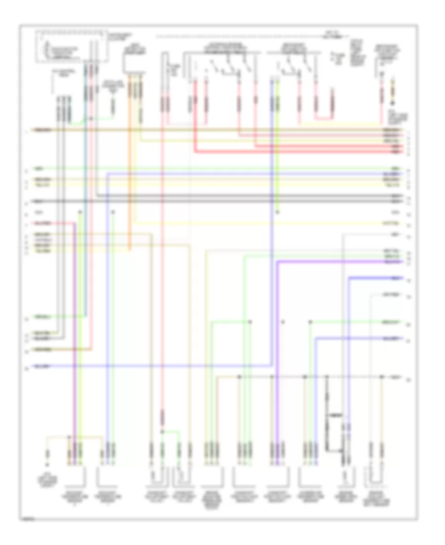
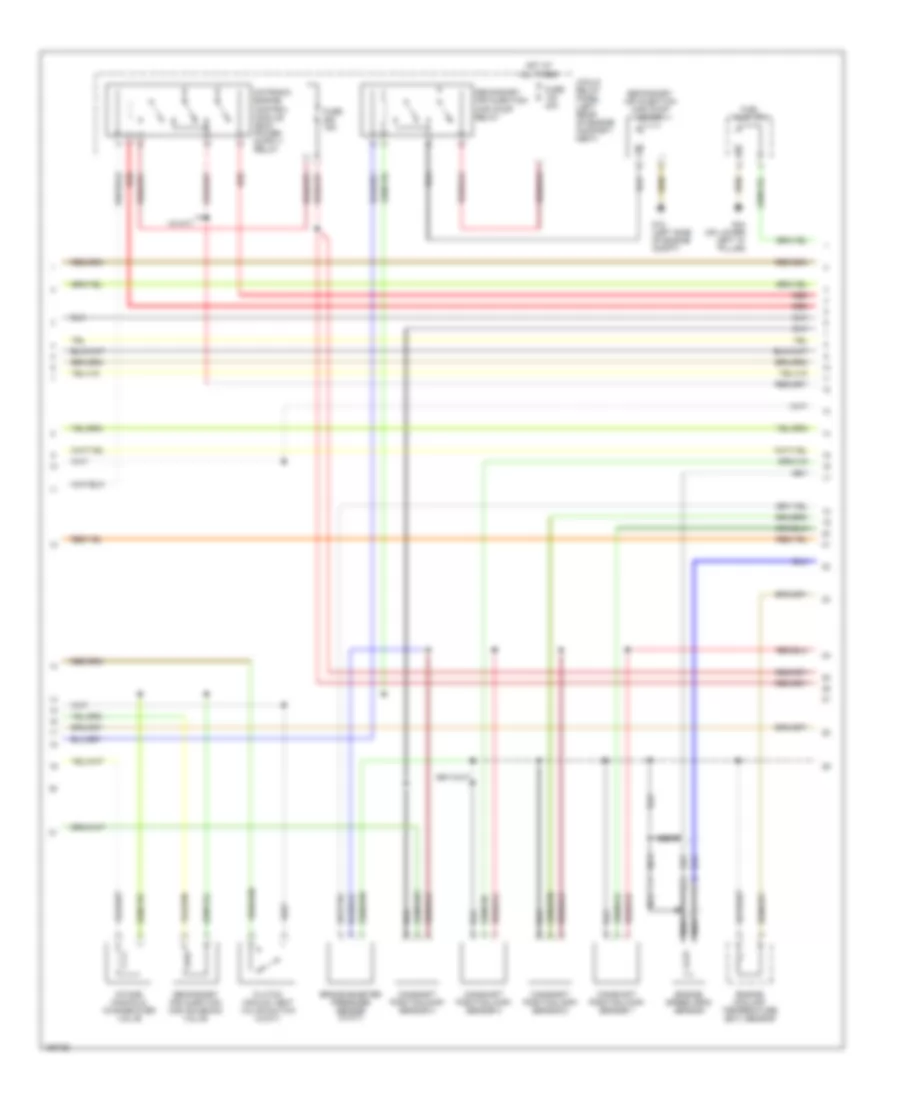
2.7L Turbo, Engine Performance Wiring Diagram (1 of 4) for Audi A6 Quattro 2004

List of elements for 2.7L Turbo, Engine Performance Wiring Diagram (1 of 4) for Audi A6 Quattro 2004:
- (behind twc) heated oxygen sensor (o2s) 2
- 13a
- Brakelight switch/ brake pedal switch
- Clutch vacuum vent valve switch (w/m/t)
- Computer data lines system
- Cruise control system
- Fuse 10a
- Fuse panel (left end of dash)
- G12 (left side of engine compt)
- Heated oxygen sensor (ho2s) 1
- Heated oxygen sensor (ho2s) 2
- Hot at all times
- Idle air control cut-off valve
- Intake air temperature (iat) sensor
- Mass airflow (maf) sensor
- Motronic engine control module (ecm) in electronic box, on leftside of fresh air plenum)
- Nca
- Red
- Secondary air injection (air) solenoid valve
- Throttle position (tp) sensor/ accelerator pedal position sensor
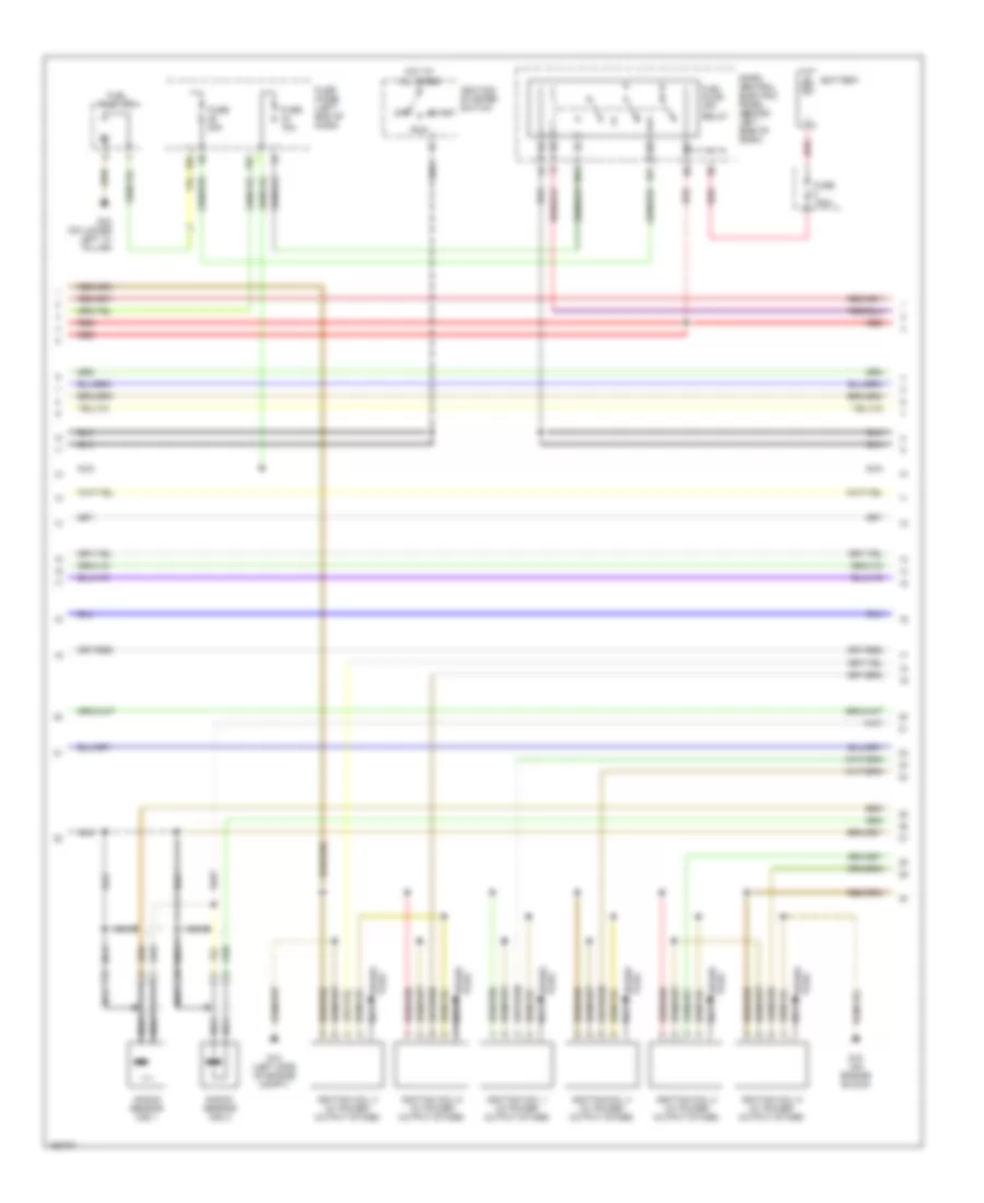
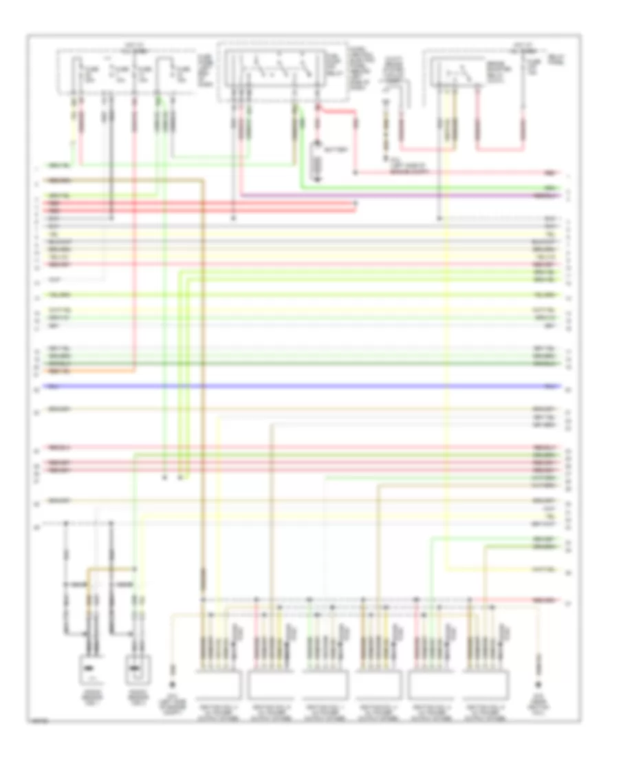
2.7L Turbo, Engine Performance Wiring Diagram (2 of 4) for Audi A6 Quattro 2004
List of elements for 2.7L Turbo, Engine Performance Wiring Diagram (2 of 4) for Audi A6 Quattro 2004:
- 3-fold relay panel (left rear of engine compt)
- A/c control head
- Brake booster pressure sensor (w/a/t)
- C15
- Camshaft adjustment valve 1
- Camshaft adjustment valve 2
- Camshaft position (cmp) sensor 1
- Camshaft position (cmp) sensor 2
- Charge air temperature sensor
- Data link connector (dlc)
- Engine coolant temperature (ect) sensor
- Engine speed (rpm) sensor
- Exhaust temperature sensor
- Fuse 15a
- Fuse 40a
- G12 (left side of engine compt)
- Hot at all times
- Instrument cluster
- Leak detection pump (ldp)
- Malfunction indicator lamp (mil)
- Nca
- Red
- Secondary air injection (air) pump motor
- Secondary air injection pump relay
- T32/1
- T32/11
- T32a/28
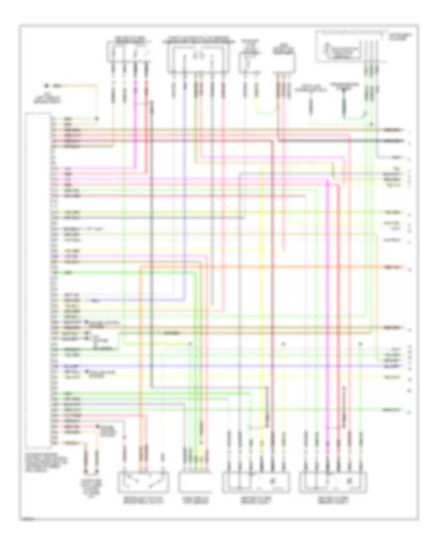
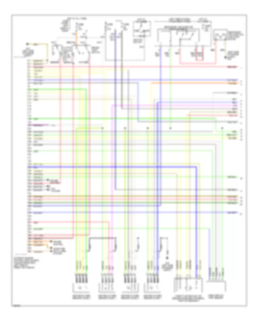
2.7L Turbo, Engine Performance Wiring Diagram (3 of 4) for Audi A6 Quattro 2004
List of elements for 2.7L Turbo, Engine Performance Wiring Diagram (3 of 4) for Audi A6 Quattro 2004:
- 28a
- 34a
- 87a
- 87f
- Battery
- Fuel pump (fp)
- Fuel pump (fp) relay
- Fuse 150a
- Fuse 15a
- Fuse 20a
- Fuse panel (left end of dash)
- G12 (left side of engine compt)
- G18 (on engine block)
- G44 (on lower left "a" pillar)
- Hot at all times
- Ignition coil 1 (w/ power output stage)
- Ignition coil 2 (w/ power output stage)
- Ignition coil 3 (w/ power output stage)
- Ignition coil 4 (w/ power output stage)
- Ignition coil 5 (w/ power output stage)
- Ignition coil 6 (w/ power output stage)
- Ignition/ starter switch
- Knock sensor (ks) 1
- Knock sensor (ks) 2
- Micro central electric panel (behind left side of dash)
- Nca
- Off
- Plug spark
- Red
- Run
- Spark plug
- Start
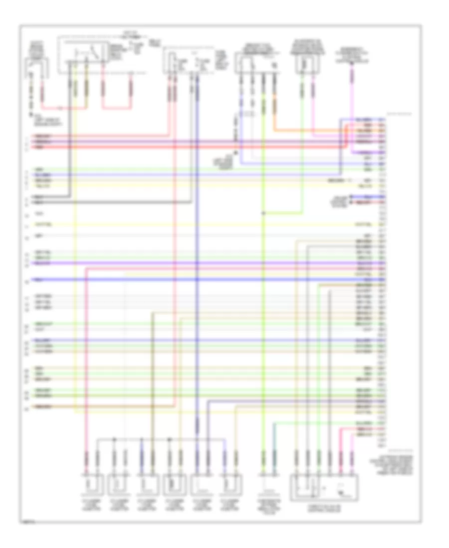
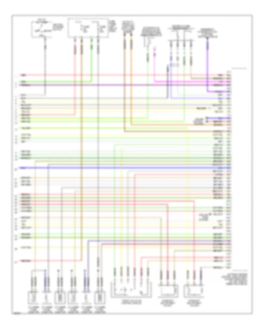
2.7L Turbo, Engine Performance Wiring Diagram (4 of 4) for Audi A6 Quattro 2004
List of elements for 2.7L Turbo, Engine Performance Wiring Diagram (4 of 4) for Audi A6 Quattro 2004:
- (behind twc) heated oxygen sensor (o2s) 1
- (w/a/t) brake system vacuum pump
- 29a
- 32a
- Brake booster relay (w/a/t)
- Cruise control system
- Cylinder 1 fuel injector
- Cylinder 2 fuel injector
- Cylinder 3 fuel injector
- Cylinder 4 fuel injector
- Cylinder 5 fuel injector
- Cylinder 6 fuel injector
- Emergency flasher switch & air bag control module
- Evaporative emission (evap) canister purge regulator valve
- Fuse 15a
- Fuse 20a
- Fuse panel (left end of dash)
- G12 (left side of engine compt)
- Hot at all times
- Motronic engine control module (ecm) (in electronic box, on left side of fresh air plenum)
- Nca
- Red
- Relay panel
- Throttle valve control module
- Wastegate bypass regulator valve
3.0L
3.0L, Engine Performance Wiring Diagram (1 of 4) for Audi A6 Quattro 2004
List of elements for 3.0L, Engine Performance Wiring Diagram (1 of 4) for Audi A6 Quattro 2004:
- A/c system (if equipped)
- Brakelight switch/ brake pedal switch
- Computer data lines system (w/ base a/t)
- Cooling fans system
- Cruise control system
- Data link connector (dlc)
- Exhaust flap valve 1 (w/ fwd)
- G12 (left side of engine compt)
- Heated oxygen sensor (ho2s) 1
- Heated oxygen sensor (ho2s) 2
- Heated oxygen sensor (o2s) 2
- Instrument cluster
- Leak detection pump (ldp)
- Malfunction indicator lamp (mil)
- Mass airflow (maf) sensor
- Motronic engine control module (ecm) in electronic box, on leftside of fresh air plenum)
- Nca
- Red
- T32/1
- T32/11
- T32a/28
- Throttle position (tp) sensor/ accelerator pedal position sensor
- Transmissions system
3.0L, Engine Performance Wiring Diagram (2 of 4) for Audi A6 Quattro 2004
List of elements for 3.0L, Engine Performance Wiring Diagram (2 of 4) for Audi A6 Quattro 2004:
- (w/a/t)
- 3-fold relay panel (left rear of engine compart- ment)
- Brake booster pressure sensor (w/a/t)
- Camshaft position (cmp) sensor 1
- Camshaft position (cmp) sensor 2
- Camshaft position (cmp) sensor 3
- Camshaft position (cmp) sensor 4
- Clutch vacuum vent valve switch (w/m/t)
- Engine coolant temperature (ect) sensor
- Engine speed (rpm) sensor
- Fuel pump (fp)
- Fuse 15a
- Fuse 40a
- G12 (left side of engine compt)
- G44 (on lower left "a" pillar)
- Hot at all times
- Intake manifold change-over valve
- Nca
- Red
- Secondary air injection (air) pump motor
- Secondary air injection (air) pump relay
- Secondary air injection (air) solenoid valve
3.0L, Engine Performance Wiring Diagram (3 of 4) for Audi A6 Quattro 2004
List of elements for 3.0L, Engine Performance Wiring Diagram (3 of 4) for Audi A6 Quattro 2004:
- (w/a/t) brake system vacuum pump
- 13a
- 28a
- 34a
- 87a
- 87f
- Battery
- Brake booster relay (w/a/t)
- Fuel pump (fp) relay
- Fuse 10a
- Fuse 15a
- Fuse 20a
- Fuse panel (left end of dash)
- G12 (left side of engine compt)
- G19 (near ignition coil)
- Hot at all times
- Ignition coil 1 (w/ power output stage)
- Ignition coil 2 (w/ power output stage)
- Ignition coil 3 (w/ power output stage)
- Ignition coil 4 (w/ power output stage)
- Ignition coil 5 (w/ power output stage)
- Ignition coil 6 (w/ power output stage)
- Knock sensor (ks) 1
- Knock sensor (ks) 2
- Micro central electric panel (behind left side of dash)
- Nca
- Plug spark
- Red
- Relay panel
- Spark plug
3.0L, Engine Performance Wiring Diagram (4 of 4) for Audi A6 Quattro 2004
List of elements for 3.0L, Engine Performance Wiring Diagram (4 of 4) for Audi A6 Quattro 2004:
- (w/ multi- tronic a/t) computer data lines system
- 29a
- 32a
- Camshaft adjustment valve 1
- Camshaft adjustment valve 2
- Cooling fans system
- Cruise control system
- Cylinder 1 fuel injector
- Cylinder 2 fuel injector
- Cylinder 3 fuel injector
- Cylinder 4 fuel injector
- Cylinder 5 fuel injector
- Cylinder 6 fuel injector
- Emergency flasher switch & air bag control module
- Evaporative emission (evap) canister purge regulator valve
- Fuse 20a
- Fuse panel (left end of dash)
- Heated oxygen sensor (o2s) 1
- Hot at all times
- Ignition/ starter switch
- Motronic engine control module (ecm) (in electronic box, on left side of fresh air plenum)
- Nca
- Off
- Red
- Run
- Start
- Throttle valve control module
4.2L
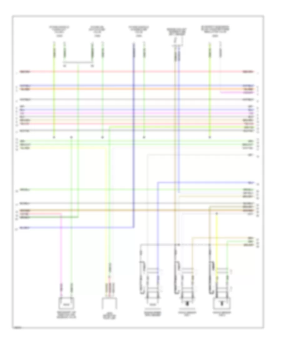
4.2L, Engine Performance Wiring Diagram (1 of 4) for Audi A6 Quattro 2004
List of elements for 4.2L, Engine Performance Wiring Diagram (1 of 4) for Audi A6 Quattro 2004:
- (left side of dash)
- (left side of dash) 3-fold relay panel
- (left side of engine compt) g12
- 13a
- 32a
- A/c system
- Brake- light switch
- Clutch vacuum vent valve switch (m/t)
- Computer data lines system
- Cruise control
- Fuse 10a
- Fuse 20a
- Fuse 40a
- Fuse panel
- G12 (left side of engine compt)
- Heated oxygen sensor (ho2s) 1
- Heated oxygen sensor (ho2s) 2
- Hot at all times
- Ignition switch
- Mass airflow (maf) sensor
- Motronic engine control module (ecm) (in electronic box, left side of fresh air plenum)
- Nca
- Off
- Red
- Run
- Secondary air injection (air) pump motor
- Secondary air injection (air) pump relay
- Start
- Throttle position (tp) sensor/accelerator pedal position sensor 2
4.2L, Engine Performance Wiring Diagram (2 of 4) for Audi A6 Quattro 2004
List of elements for 4.2L, Engine Performance Wiring Diagram (2 of 4) for Audi A6 Quattro 2004:
- Engine coolant temperature (ect) sensor
- Engine speed (rpm) sensor
- Evaporative emission (evap) canister purge regulator valve
- Intake air switch-over valve
- Intake manifold change-over valve
- Intake manifold tuning (imt) valve 2
- Knock sensor (ks) 1
- Knock sensor (ks) 2
- Leak detection pump (ldp)
- Nca
- Secondary air injection (air) solenoid valve
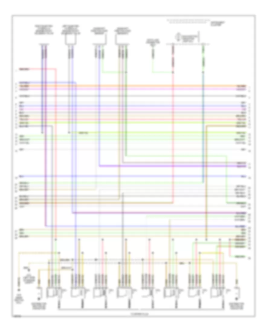
4.2L, Engine Performance Wiring Diagram (3 of 4) for Audi A6 Quattro 2004
List of elements for 4.2L, Engine Performance Wiring Diagram (3 of 4) for Audi A6 Quattro 2004:
- (mil)
- Camshaft position (cmp) sensor
- Camshaft position (cmp) sensor 2
- Coil
- Data link connector (dlc)
- Distributor ignition (di) capacitor
- G12 (left side of engine compt)
- G19 (near ignition coil)
- Instrument cluster
- Left electro- hydraulic engine mount solenoid valve
- Malfunction indicator lamp
- Nca
- Right electro- hydraulic engine mount solenoid valve
- T32/11
- T32a/28
- To spark plug
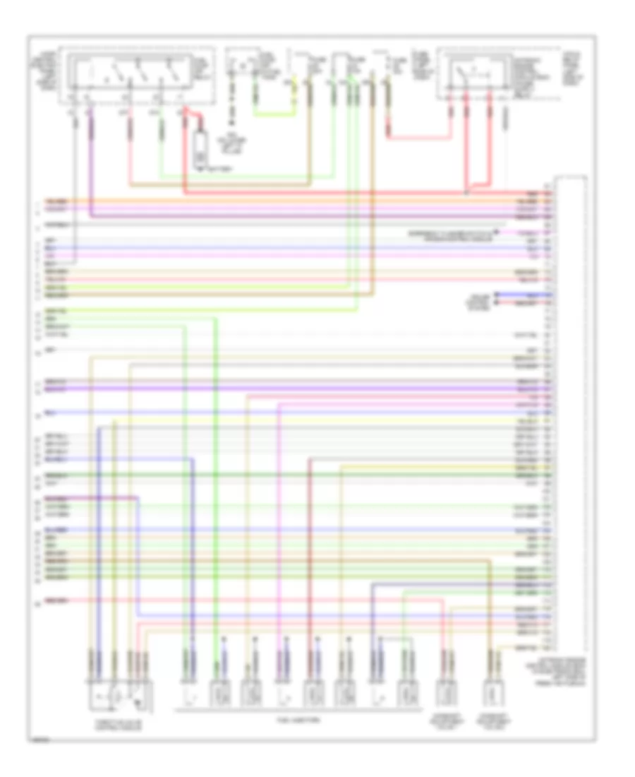
4.2L, Engine Performance Wiring Diagram (4 of 4) for Audi A6 Quattro 2004
List of elements for 4.2L, Engine Performance Wiring Diagram (4 of 4) for Audi A6 Quattro 2004:
- 3-fold relay panel (left side of dash)
- 87a
- 87f
- Battery
- Camshaft adjustment valve 1
- Camshaft adjustment valve 2
- Cruise control system
- Emergency flasher switch & air bag control module
- Fuel injectors
- Fuel pump (fp) (in fuel tank)
- Fuel pump (fp) relay
- Fuse 15a
- Fuse 20a
- Fuse 30a
- Fuse panel (left side of dash)
- G44 (on lower left "a" pillar)
- Micro central electric panel (left side of dash)
- Motronic engine control module (ecm) (in electronic box, left side of fresh air plenum)
- Red
- Throttle valve control module