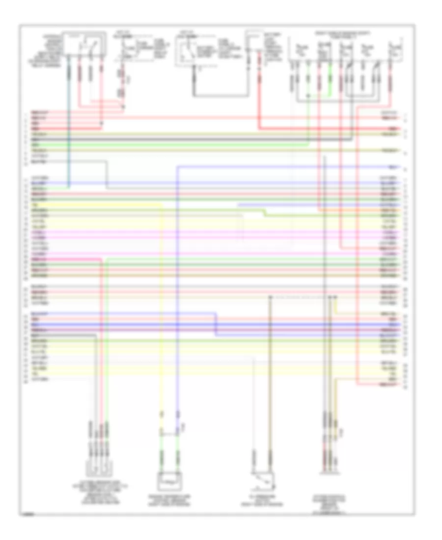
ENGINE PERFORMANCE
3.0L SC
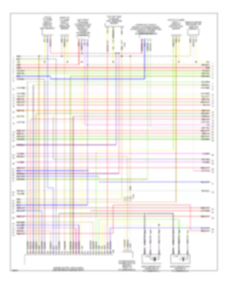
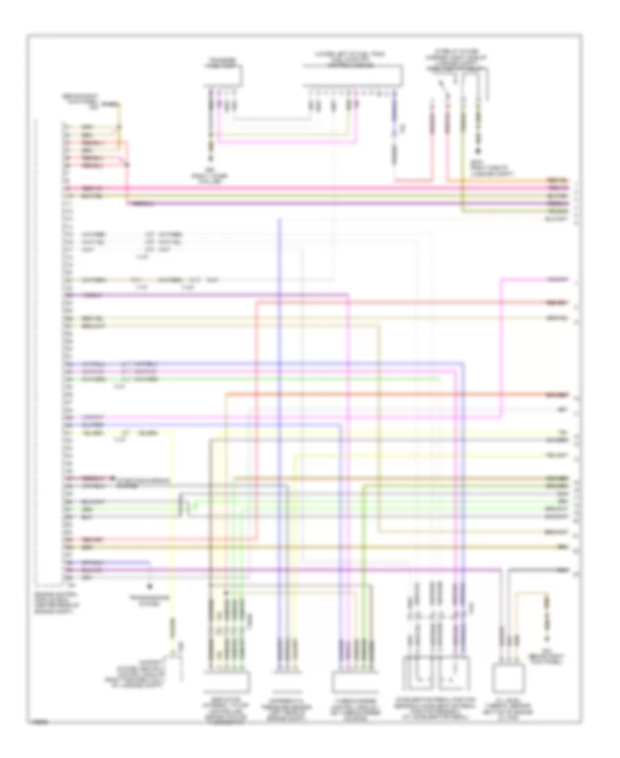
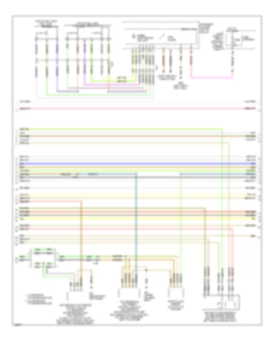
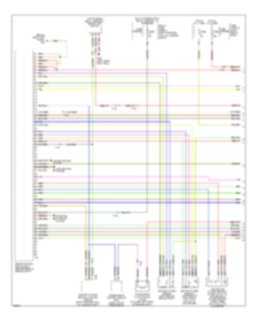
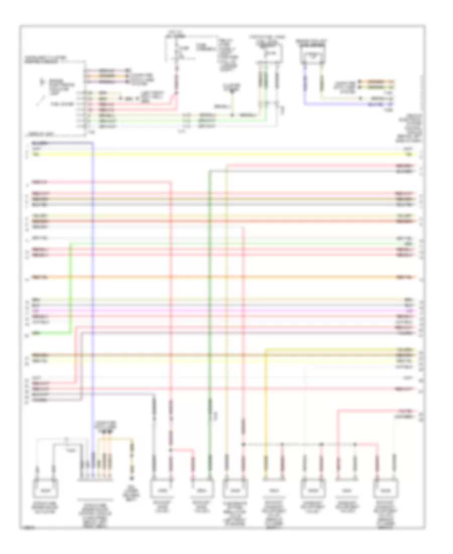
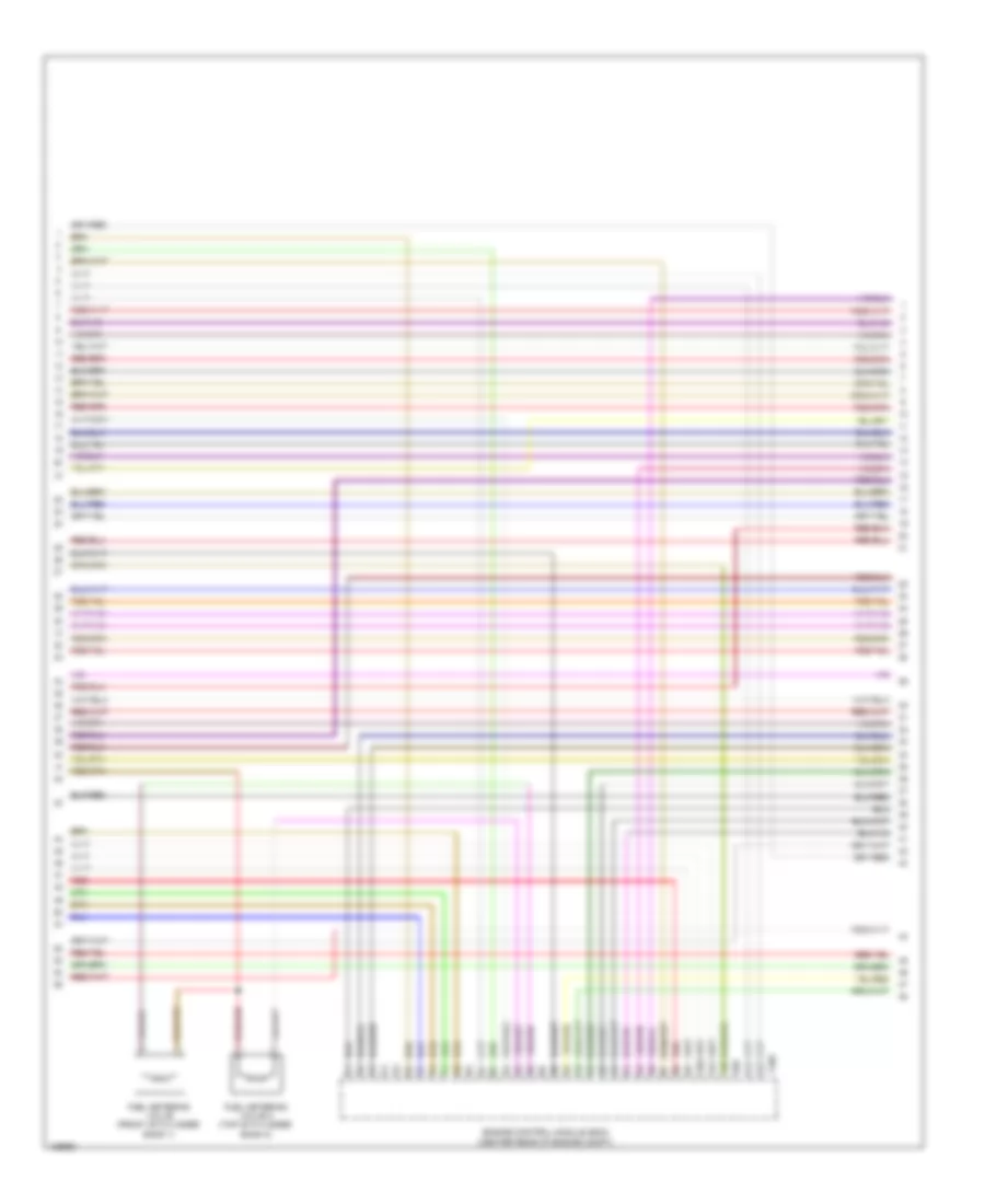
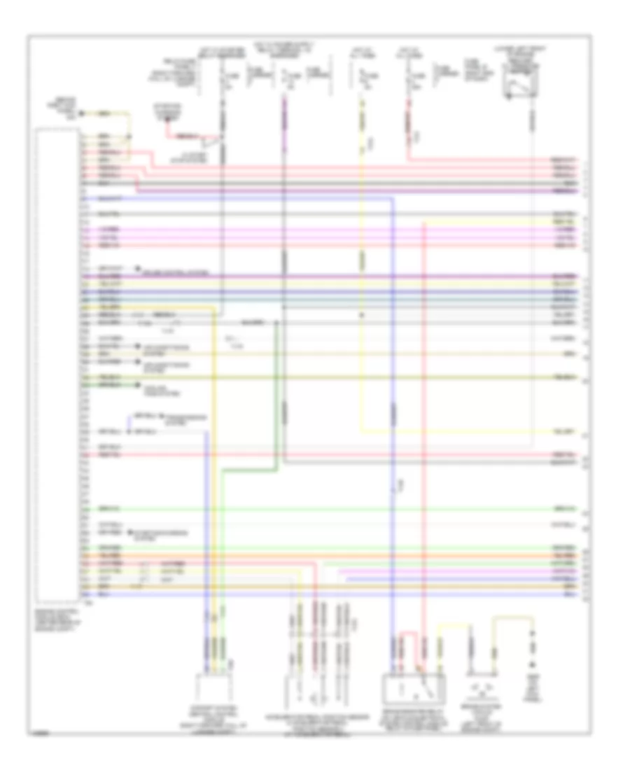
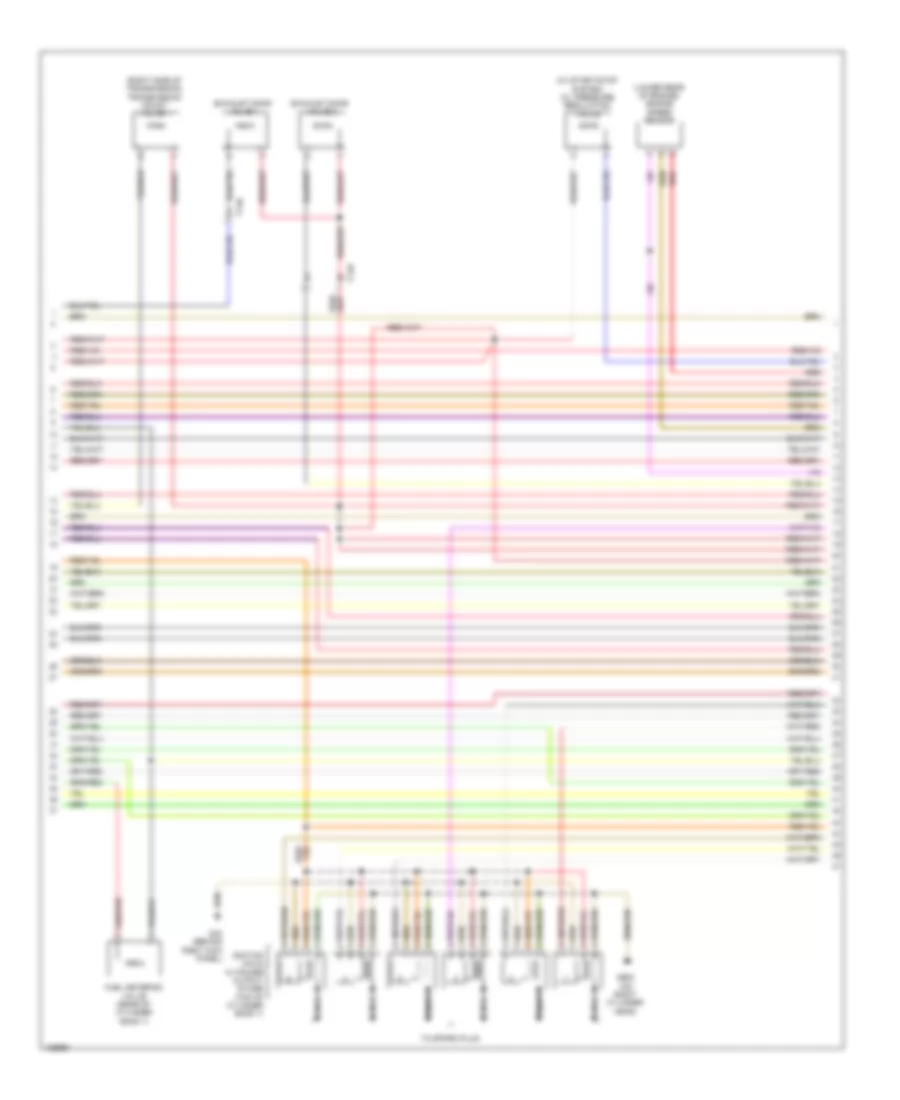
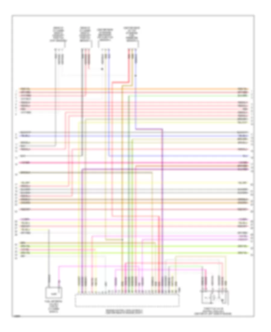
3.0L SC, Engine Performance Wiring Diagram (1 of 9) for Audi A8 Quattro L TDI 2014

List of elements for 3.0L SC, Engine Performance Wiring Diagram (1 of 9) for Audi A8 Quattro L TDI 2014:
- (behind right kick panel) g43
- Accelerator pedal position sensor & accelerator pedal position (app) sensor 2 (at accelerator pedal)
- Comfort system central control module (right forward wall of luggage compt)
- Computer data lines system
- Cooling fan control module
- Cooling fan control module 2
- Cooling fans system
- Engine control module (ecm) (center rear of engine compt)
- Fuse 15a
- Fuse 5a
- Fuse panel a (right side of engine compt)
- G43 (behind right kick panel)
- Nca
- Oil level thermal sensor (bottom of engine oil pan)
- Oxygen sensor (02s) 2 after catalytic converter (twc) & oxygen sensor (o2s) 2 after catalytic converter heater
- Red
- Starting/ charging system
- Starting/charging system
- T17f
- T17k
- T2t
- T2u
- T32c
- T32d
- T94
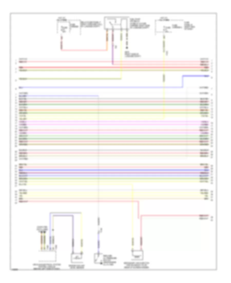
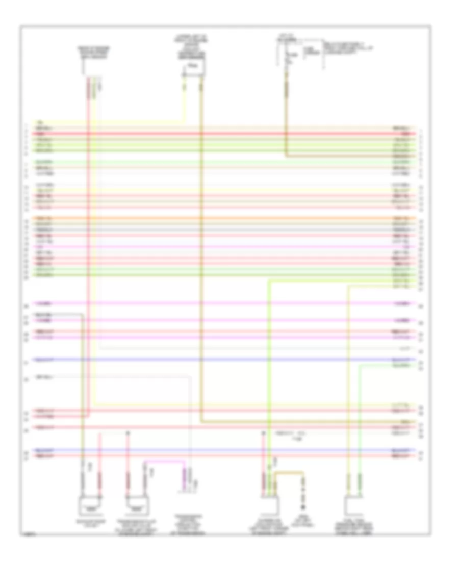
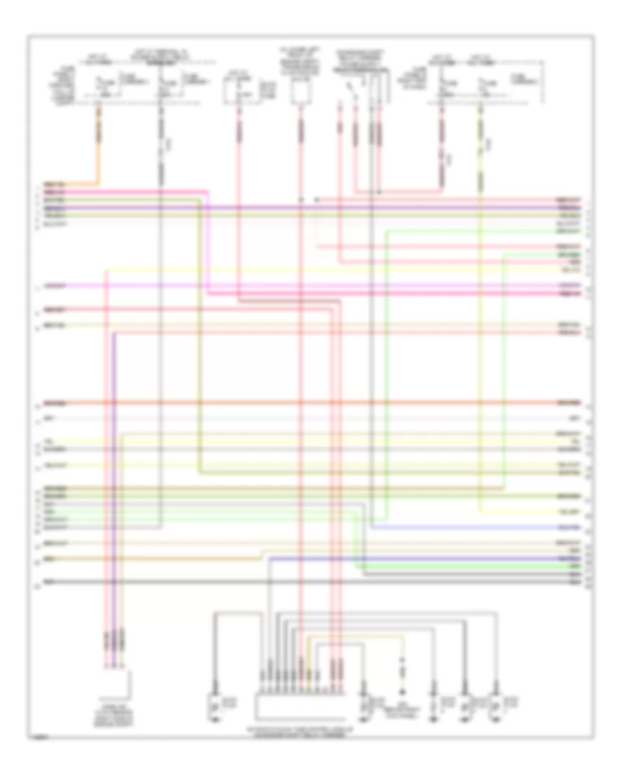
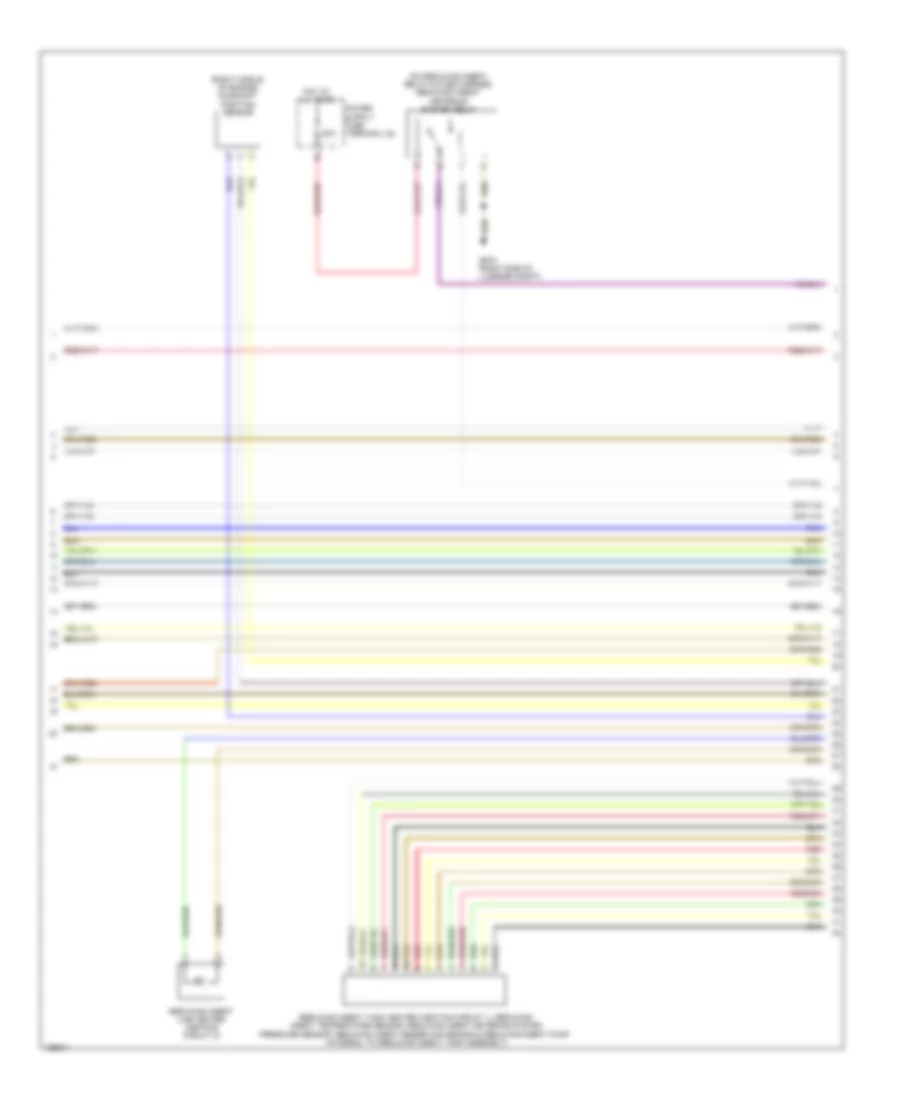
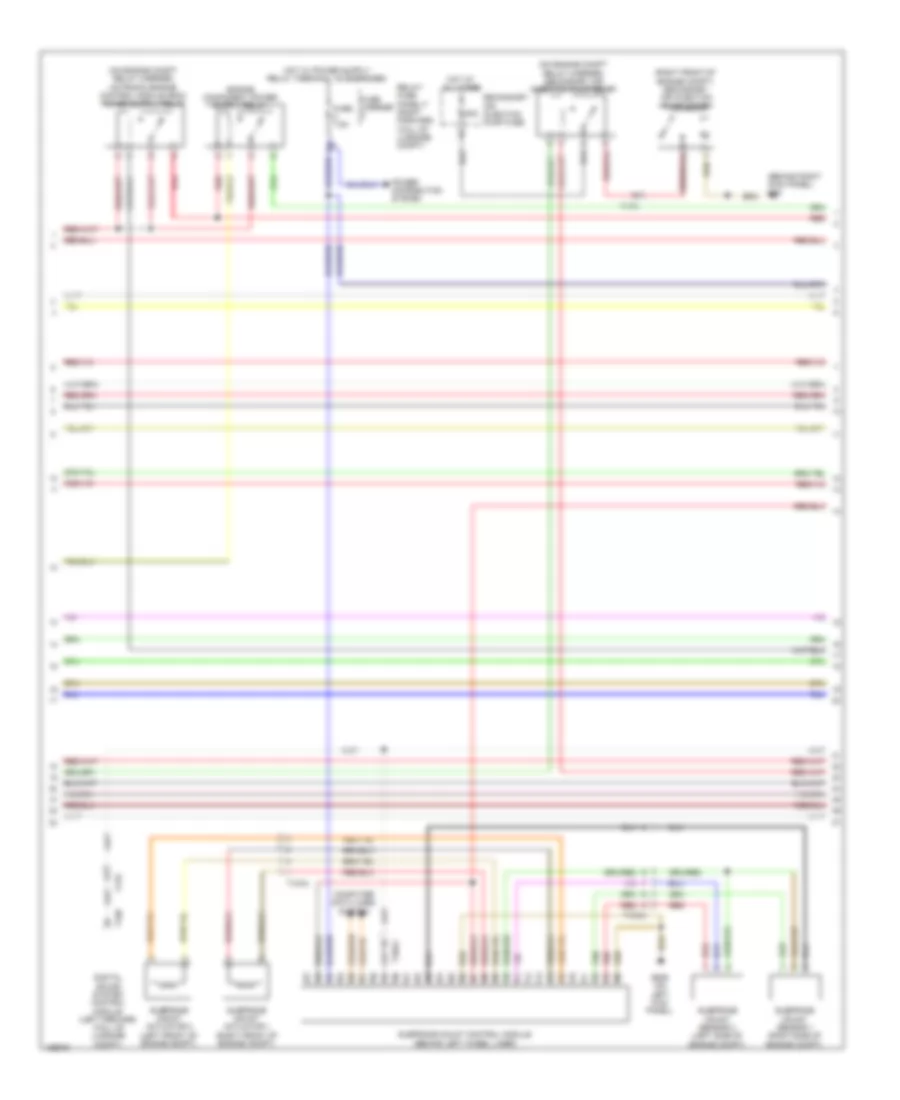
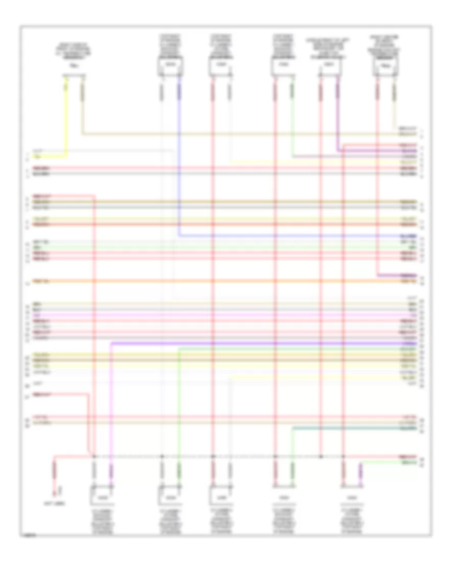
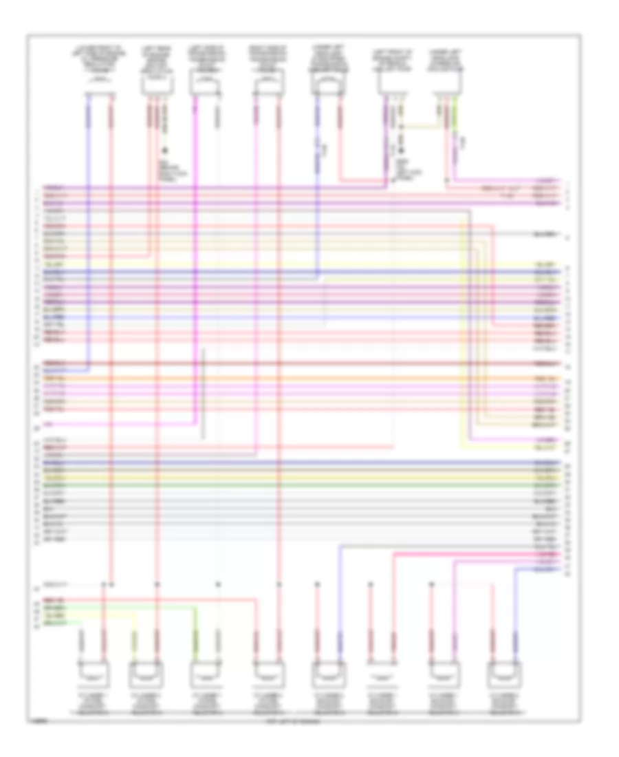
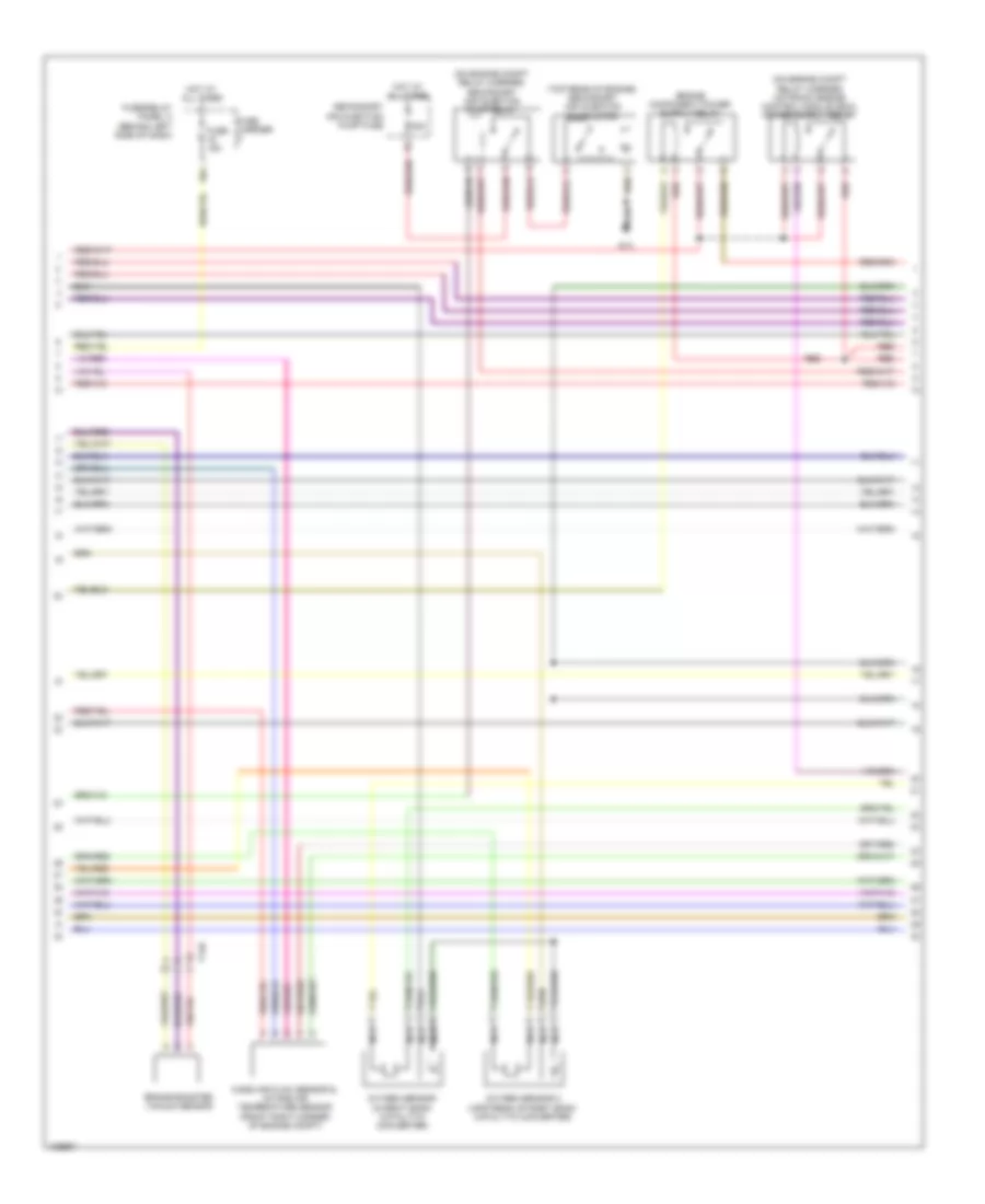
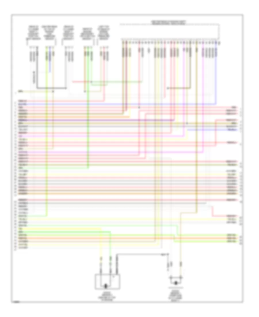
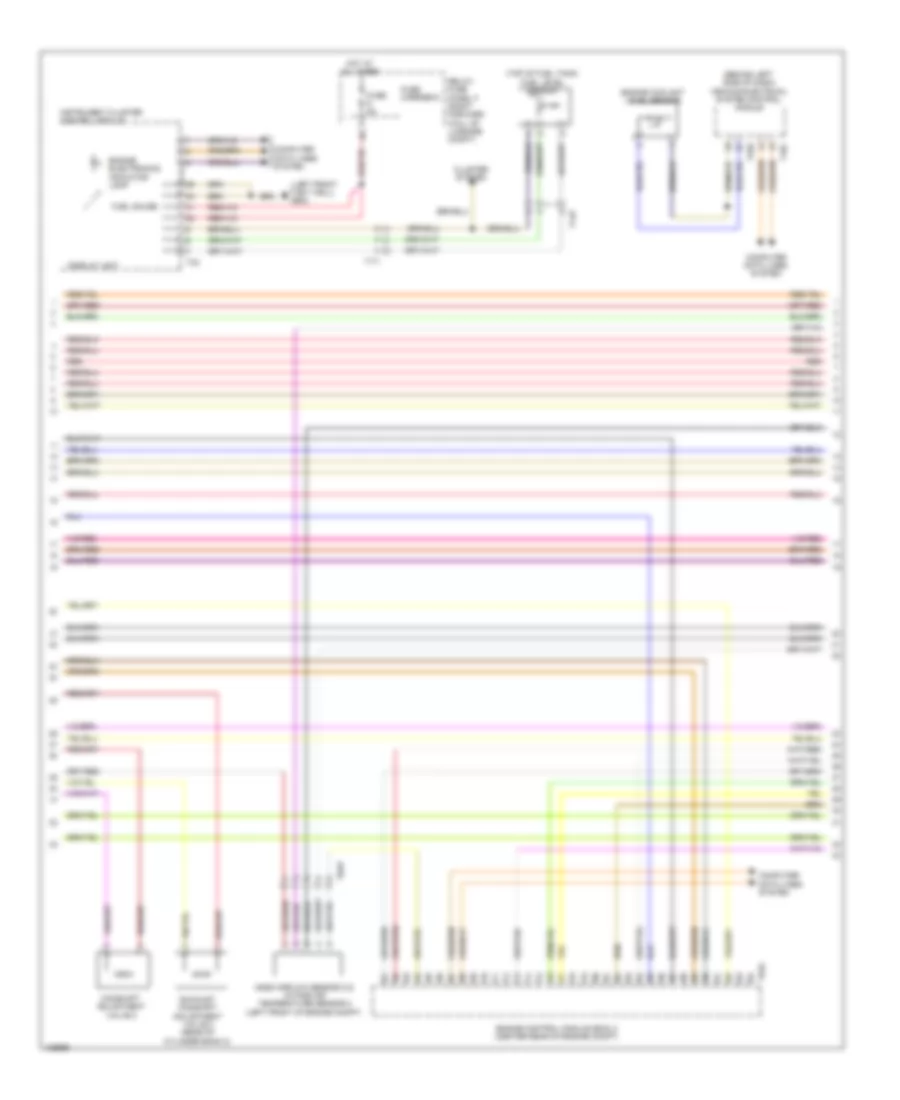
3.0L SC, Engine Performance Wiring Diagram (2 of 9) for Audi A8 Quattro L TDI 2014
List of elements for 3.0L SC, Engine Performance Wiring Diagram (2 of 9) for Audi A8 Quattro L TDI 2014:
- (right side of engine compt) fuse panel a
- 10a
- 11a
- 12a
- Battery interrupt igniter
- Battery jump start terminal (terminal 30 wire
- Engine temperature control sensor (right side of engine)
- Fuse 10a
- Fuse 15a
- Fuse 20a (or 30a)
- Fuse 35a
- Fuse carrier
- Fuse panel b (right end of dash)
- Fuse panel d (in luggage compt, on battery)
- Hot at all times
- Intake manifold runner position sensor (front of cylinder bank 1)
- Junction 2)
- Nca
- Oil pressure switch (right side of engine)
- Oxygen sensor (o2s) after three way catalytic converter & oxygen sensor (o2s) 1 after catalytic converter heater
- Red
- T14k
- T17f
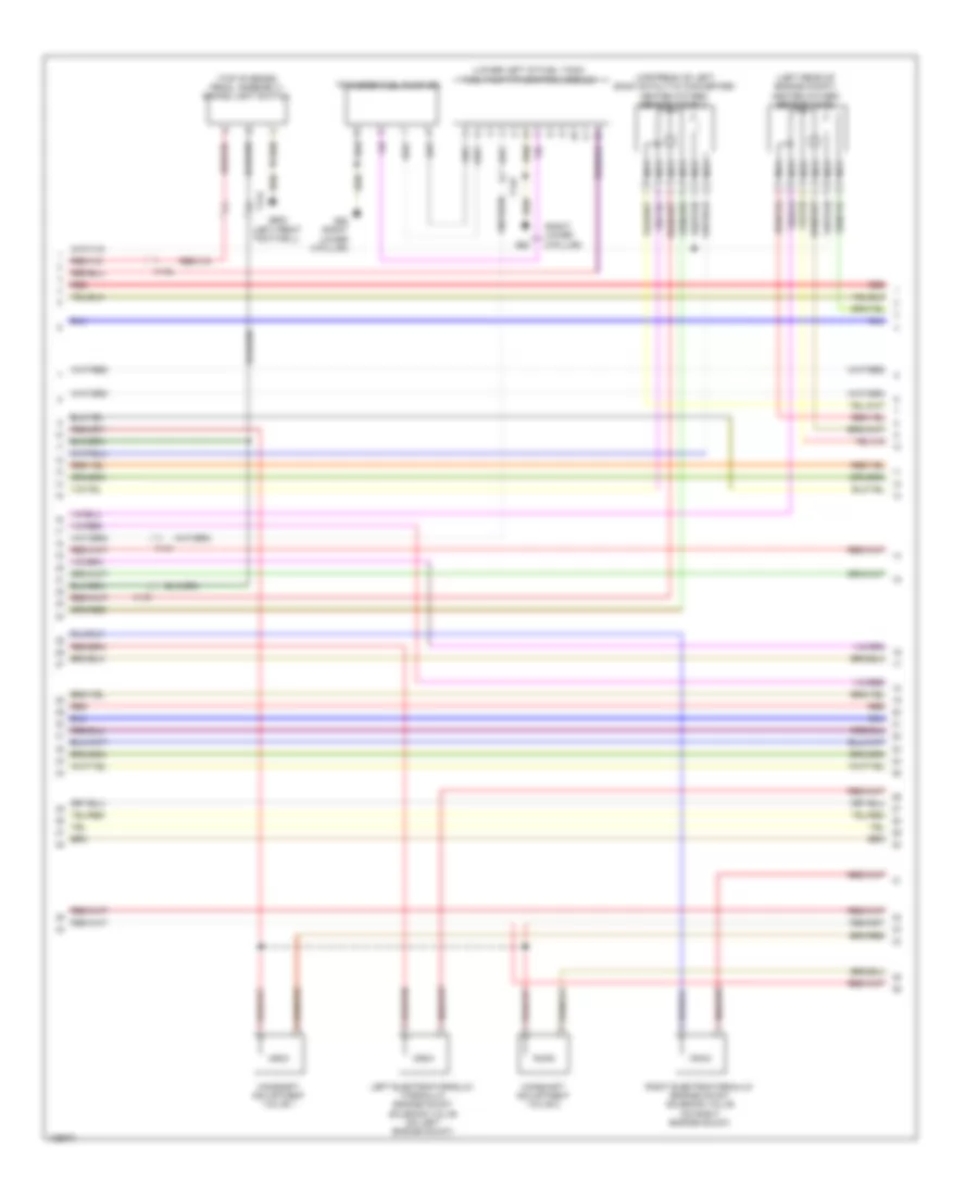
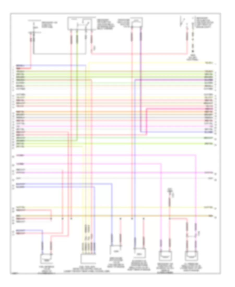
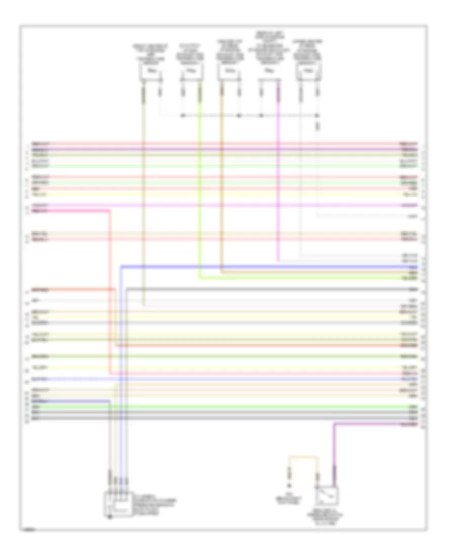
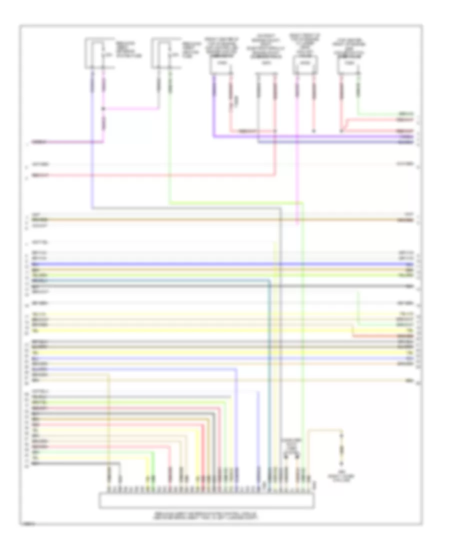
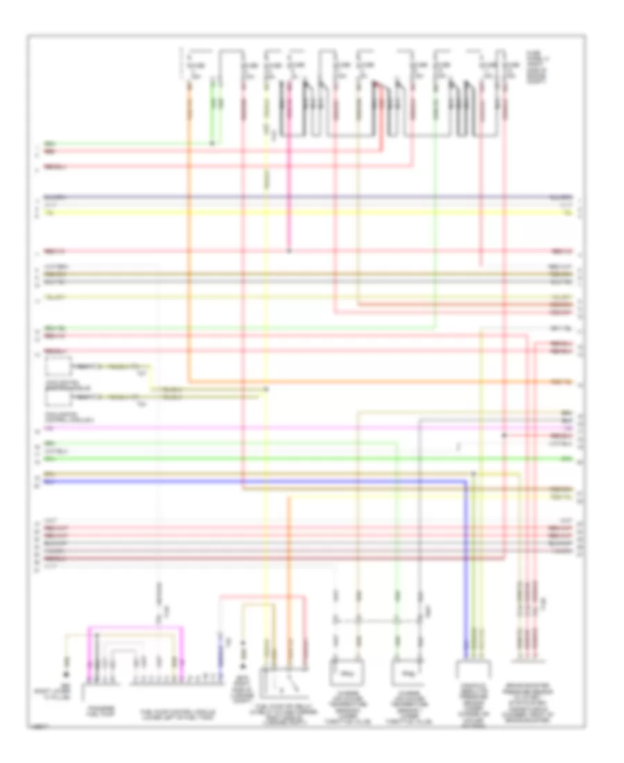
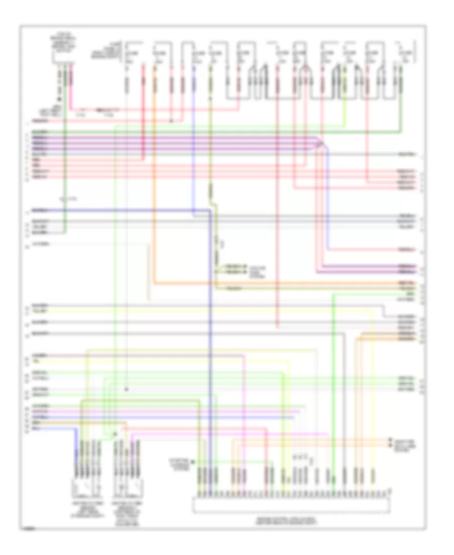
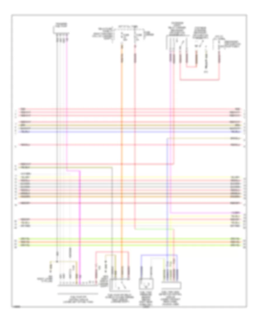
3.0L SC, Engine Performance Wiring Diagram (3 of 9) for Audi A8 Quattro L TDI 2014
List of elements for 3.0L SC, Engine Performance Wiring Diagram (3 of 9) for Audi A8 Quattro L TDI 2014:
- 15a
- Computer data lines system
- Engine coolant level sensor
- Fuel pump (fp) relay (in relay & fuse carrier, right side of luggage compt)
- Fuse 25a
- Fuse 5a
- Fuse carrier
- Fuse carrier 2
- Fuse panel b (right end of dash)
- G675 (right side of luggage compt)
- Hot at all times
- Red
- Reduced oil pressure switch (near engine oil filter)
- Relay/fuse panel f (right forward wall of luggage compt)
- Secondary air injection (air) solenoid valve (rear of supercharger)
- T14d
- T16c
- T17g
- T32b
- T3x
- Vehicle electrical system control module (behind left side of dash)
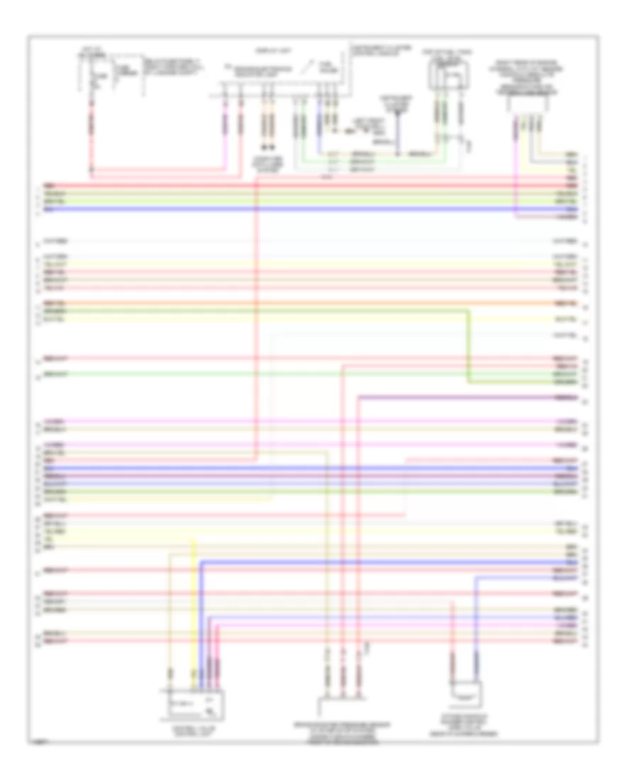
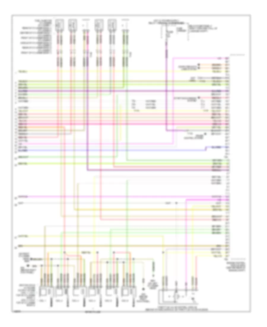
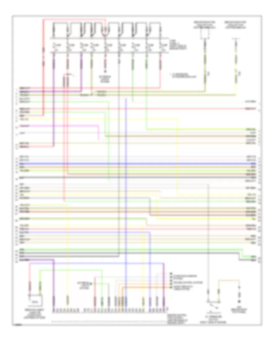
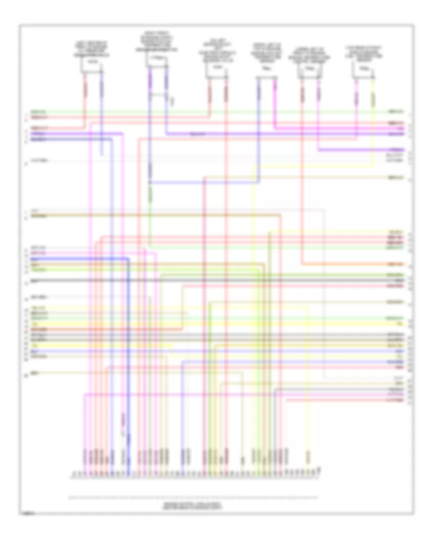
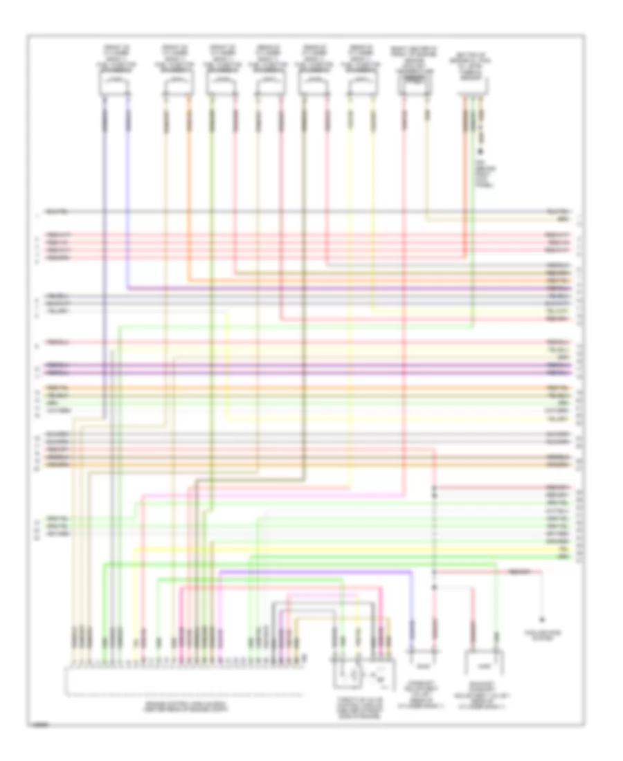
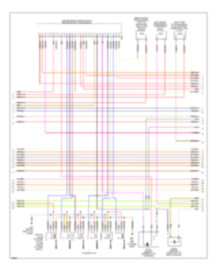
3.0L SC, Engine Performance Wiring Diagram (4 of 9) for Audi A8 Quattro L TDI 2014
List of elements for 3.0L SC, Engine Performance Wiring Diagram (4 of 9) for Audi A8 Quattro L TDI 2014:
- (left rear of engine compt) heated oxygen sensor (h02s)
- (lower left of fuel tank) fuel pump (fp) control module
- (right lower c-pillar)
- (top of brake pedal assembly) brake light switch
- (upstream of left bank catalytic converter)
- Camshaft adjustment valve 1
- Camshaft adjustment valve 2
- G602 (left front footwell)
- G62
- G62 (right lower c-pillar)
- Heated oxygen sensor (ho2s) 2
- Left electrohydraulic hydraulic engine mount solenoid valve (on left engine mount)
- Nca
- Red
- Right electrohydraulic engine mount solenoid valve (on right engine mount)
- T14p
- T17f
- T17g
- T17k
- Transfer fuel pump (fp)
3.0L SC, Engine Performance Wiring Diagram (5 of 9) for Audi A8 Quattro L TDI 2014
List of elements for 3.0L SC, Engine Performance Wiring Diagram (5 of 9) for Audi A8 Quattro L TDI 2014:
- (left front footwell) g602
- (right rear of engine, integral with iat sensor) manifold absolute pressure sensor/intake air temperature sensor
- (top of fuel tank) fuel level sensor
- Brake booster pressure sensor (w/ start/stop system) (inside plenum chamber, front of brake booster)
- Computer data lines system
- Control valve control unit
- Display unit
- Engine electronics indicator lamp
- Fuel gauge
- Fuse 5a
- Fuse carrier
- Hot at all times
- Instrument cluster control module
- Instrument cluster system
- Intake manifold runner control (imrc) valve (rear of supercharger)
- Red
- Relay/fuse panel f (right forward wall of luggage compt)
- T14b
- T14p
- T17i
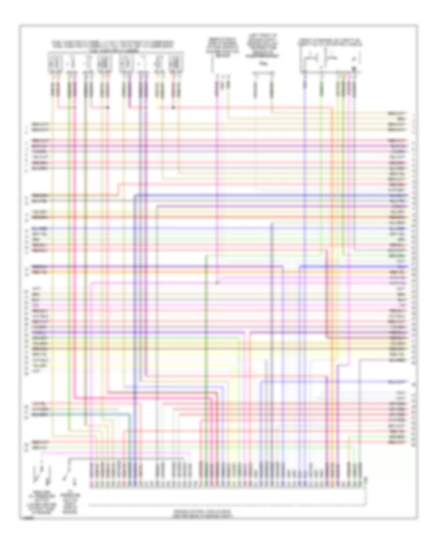
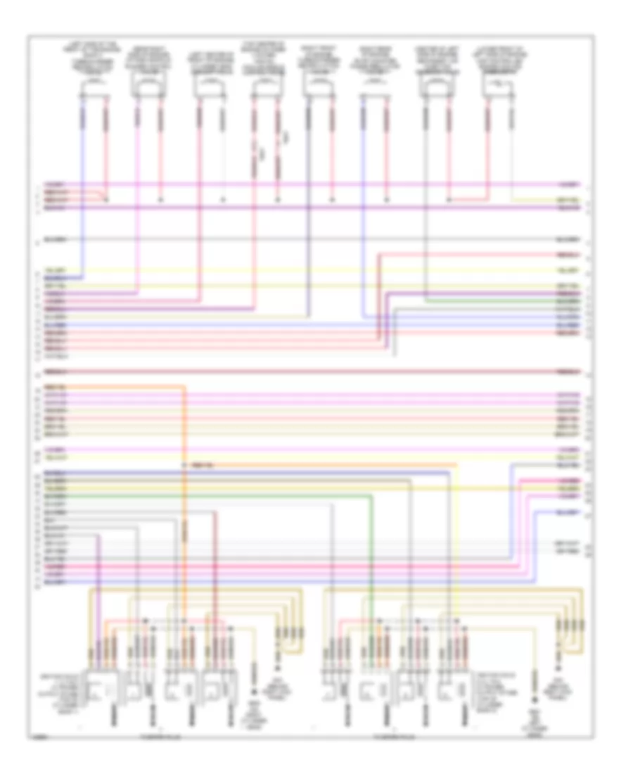
3.0L SC, Engine Performance Wiring Diagram (6 of 9) for Audi A8 Quattro L TDI 2014
List of elements for 3.0L SC, Engine Performance Wiring Diagram (6 of 9) for Audi A8 Quattro L TDI 2014:
- (front of cylinder bank 1) low fuel pressure sensor
- (left front of engine) intake manifold temperature sensor 2 & charge air pressure sensor 2
- (rear of engine) secondary air injection sensor 1
- (top left side of engine) fuel pressure sensor
- (top of cylinder bank 1) camshaft position (cmp) sensor
- (top of cylinder bank 2) camshaft position (cmp) sensor 2
- (upper right side of engine, on supercharger) intake manifold temperature sensor & charge air pressure sensor
- Engine control module (ecm) (center rear of engine compt)
- Intake manifold runner position sensor 2 (front of cylinder bank 2)
- Knock sensor (ks) 1 (inner side of cylinder bank 1)
- Knock sensor (ks) 2 (center of cylinder bank 2)
- Nca
- Red
- T14d
- T14k
- T60
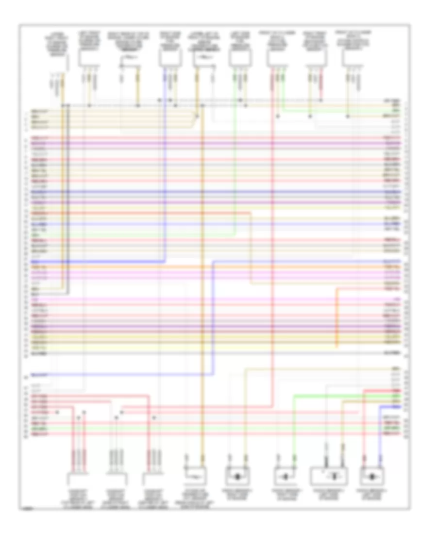
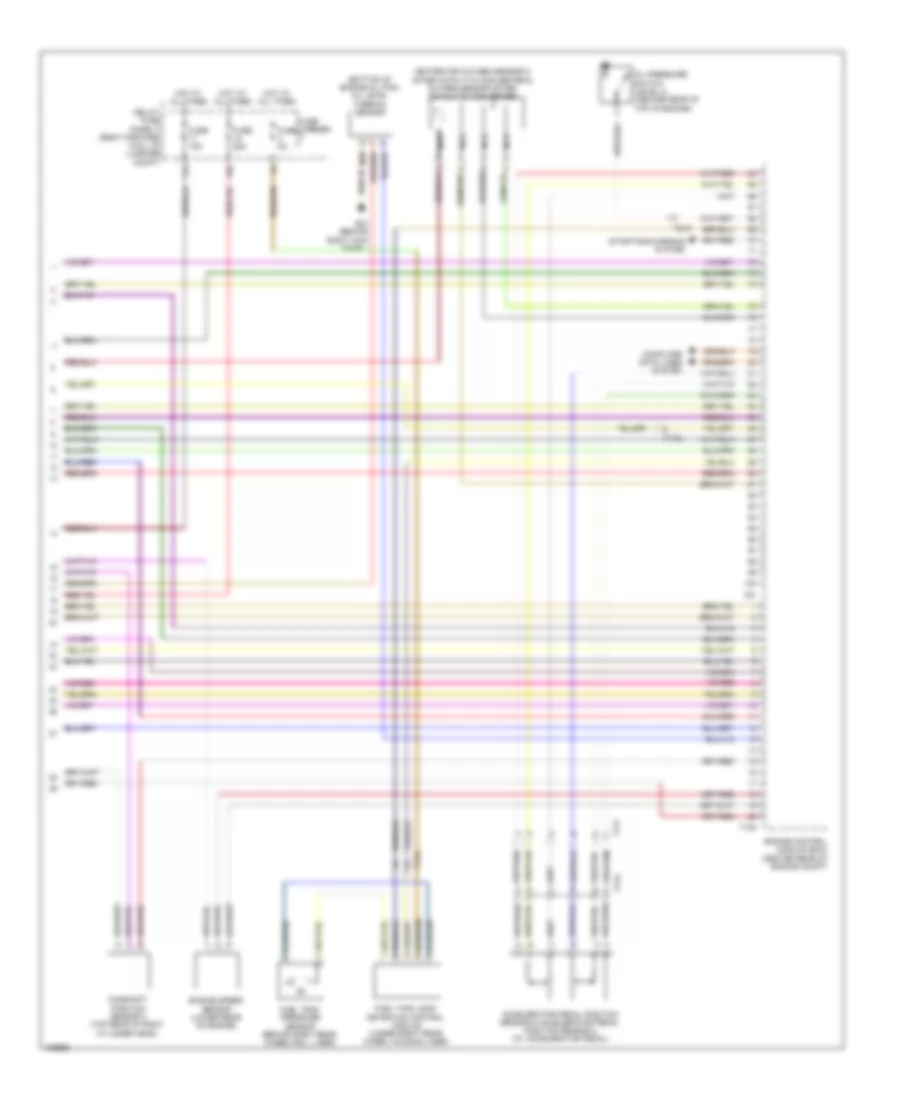
3.0L SC, Engine Performance Wiring Diagram (7 of 9) for Audi A8 Quattro L TDI 2014
List of elements for 3.0L SC, Engine Performance Wiring Diagram (7 of 9) for Audi A8 Quattro L TDI 2014:
- (rear of engine) engine speed (rpm) sensor
- (upper left of front of engine) engine coolant temperature (ect) sensor
- Charge air cooling pump (left front corner of engine compt)
- Exhaust door valve 1
- Fuel tank pressure sensor (behind right rear wheelwell liner)
- Fuse 5a
- Fuse carrier
- G639 (on left kick panel)
- Hot at all times
- Red
- Relay/fuse panel f (right forward wall of luggage compt)
- T14b
- T16a
- Transmission control module (tcm) (in bottom of transmission)
- Transmission fluid cooling valve (in lower left front of engine compt)
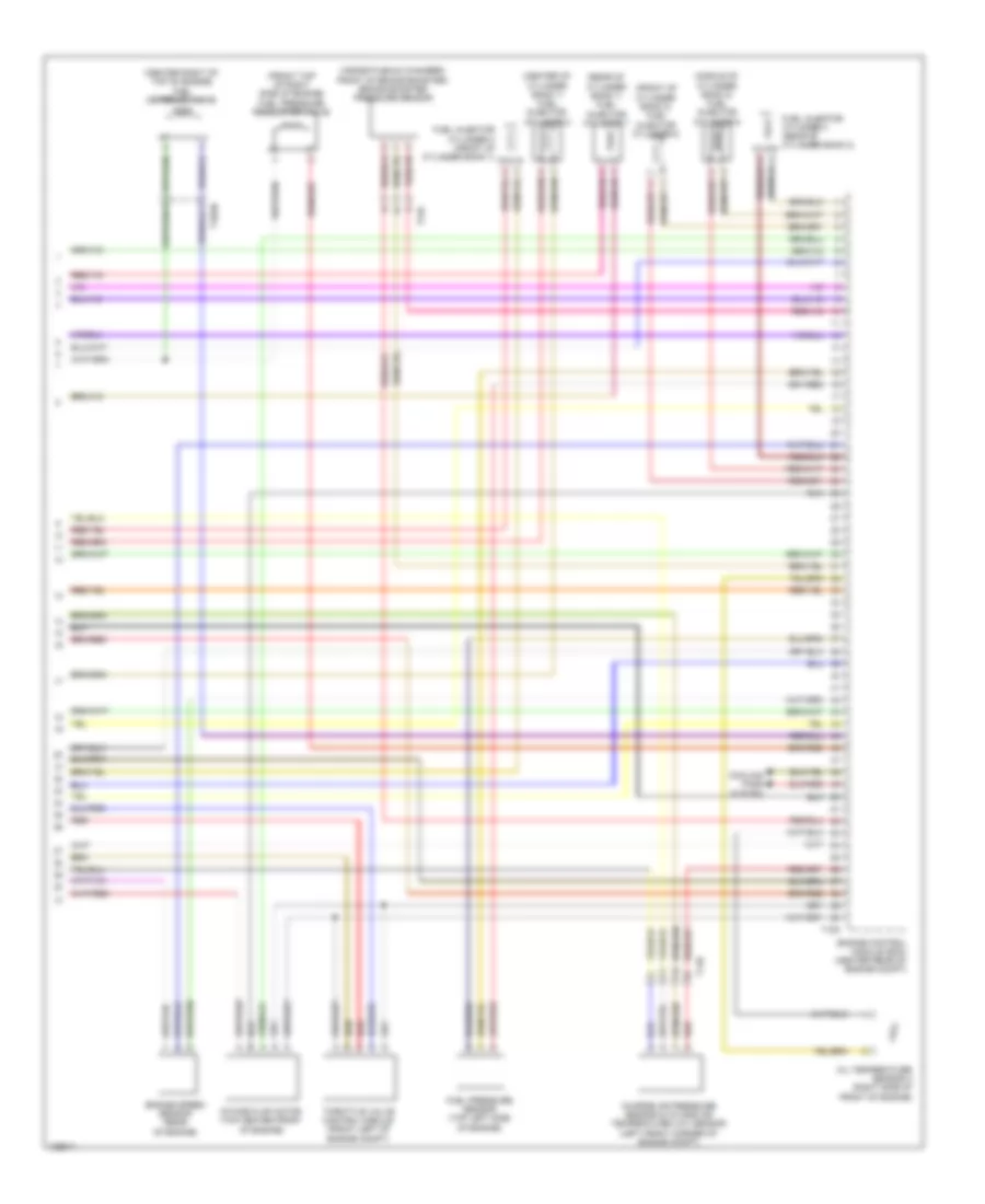
3.0L SC, Engine Performance Wiring Diagram (8 of 9) for Audi A8 Quattro L TDI 2014
List of elements for 3.0L SC, Engine Performance Wiring Diagram (8 of 9) for Audi A8 Quattro L TDI 2014:
- (not used)
- 50a
- Crankcase ventilation shut-off valve
- Egr cooler switch-over valve (top center of front of engine)
- Evaporative emission (evap) canister purge regulator valve 1 (right rear of engine)
- Fuel metering valve (front of cylinder bank 1)
- Fuel tank leak detection control module (under the right rear wheel housing liner)
- G639 (on left kick panel)
- Oil pressure regulation valve (lower front of left side of engine)
- Red
- Secondary air injection (air) pump motor (left front of engine compt)
- Secondary air injection (air) pump relay (on engine compt relay carrier)
- Secondary air injection (air) solenoid valve 2 (rear of supercharger)
- Secondary air injection pump fuse
- T14d
- T17g
- T2cf
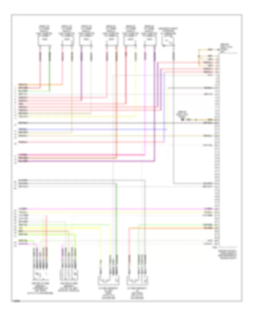
3.0L SC, Engine Performance Wiring Diagram (9 of 9) for Audi A8 Quattro L TDI 2014
List of elements for 3.0L SC, Engine Performance Wiring Diagram (9 of 9) for Audi A8 Quattro L TDI 2014:
- (not used)
- (on right cylinder head) g600
- 14a
- Coil 1
- Coil 2
- Coil 3
- Coil 4
- Coil 5
- Coil 6
- Computer data lines system
- Cruise control system
- Engine control module (ecm) (center rear of engine compt)
- Fuel injector cylinders (cylinder 1: rear of cylinder bank 1) (cylinder 2: center of cylinder bank 1 (cylinder 6: front of cylinder bank 2) (cylinder 5: middle of cylinder bank 2) (cylinder 4: rear of cylinder bank 2) (cylinder 3: front of cylinder bank 1)
- Fuse 5a
- Fuse carrier
- G43 (behind right kick panel)
- G601 (on left cylinder head)
- Ignition coils w/ power output stage (coil 1, 2 & 3: top of cylinder bank 1) (coil 4, 5 & 6: top of cylinder bank 2)
- Nca
- Relay/fuse panel f (right forward wall of luggage compt)
- Spark plugs
- Starting/charging system
- T14d
- T14k
- T17f
- T17g
- T17k
- T60
- T94
- Throttle valve control module (behind intake manifold, on throttle valve housing)
3.0L TURBO DIESEL
3.0L Turbo Diesel, Engine Performance Wiring Diagram (1 of 9) for Audi A8 Quattro L TDI 2014
List of elements for 3.0L Turbo Diesel, Engine Performance Wiring Diagram (1 of 9) for Audi A8 Quattro L TDI 2014:
- (behind right kick panel) g43
- (in relay & fuse carrier, right side of luggage compt) fuel pump (fp) relay
- (lower left of fuel tank) fuel pump (fp) control module
- Accelerator pedal position sensor & accelerator pedal position sensor 2 (at accelerator pedal)
- Comfort system central control module (right forward wall of luggage compt)
- Differential pressure sensor (left rear of engine compt)
- Egr motor (integral to map controlled engine cooling thermostat)
- Engine control module (ecm) (center rear of engine compt)
- G43 (behind right kick panel)
- G62 (right lower c-pillar)
- G675 (right side of luggage compt)
- Oil level thermal sensor (bottom of engine oil pan)
- Starting/charging system
- T10an
- T14p
- T17f
- T17k
- T32c
- T3x
- T91
- Transfer fuel pump
- Transmissions system
- Turbocharger control module 1 (on turbocharger housing)
3.0L Turbo Diesel, Engine Performance Wiring Diagram (2 of 9) for Audi A8 Quattro L TDI 2014
List of elements for 3.0L Turbo Diesel, Engine Performance Wiring Diagram (2 of 9) for Audi A8 Quattro L TDI 2014:
- (in lower left front of engine compt) transmission fluid cooling valve
- 14a
- 15a
- 80a
- Automatic glow time control module (on engine compt relay carrier)
- Fuse 25a
- Fuse 35a
- Fuse 5a
- Fuse carrier 1
- Fuse carrier 2
- Fuse carrier 3
- Fuse panel b (right end of dash)
- Fuse panel f (right forward wall of luggage compt)
- G43 (behind right kick panel)
- Glow plug
- Glow plug fuse
- Hot at all times
- Mass air flow sensor (right side of engine compt)
- Red
- T17f
- T17g
3.0L Turbo Diesel, Engine Performance Wiring Diagram (3 of 9) for Audi A8 Quattro L TDI 2014
List of elements for 3.0L Turbo Diesel, Engine Performance Wiring Diagram (3 of 9) for Audi A8 Quattro L TDI 2014:
- (center top of rear of engine) exhaust gas temperature sensor 1
- (front center of top of engine) egr temperature sensor
- (in output of scr) exhaust gas temperature sensor 4
- (rear of left side of engine compt) (w/ emissions standard bin 5/ulev) exhaust gas temperature sensor 2
- (upper center of rear of engine) exhaust gas temperature sensor 3
- Cylinder 2 combustion chamber pressure sensor & glow plug 2 (if equipped)
- G43 (behind right kick panel)
- Red
- Reduced oil pressure switch (near engine oil filter)
3.0L Turbo Diesel, Engine Performance Wiring Diagram (4 of 9) for Audi A8 Quattro L TDI 2014
List of elements for 3.0L Turbo Diesel, Engine Performance Wiring Diagram (4 of 9) for Audi A8 Quattro L TDI 2014:
- (behind radiator) coolant fan control module
- (behind radiator) coolant fan control module 2
- 10a
- 11a
- Computer data lines system
- Cruise control system
- Engine control module (ecm) (center rear of engine compt)
- Exterior lights system
- Fuse 10a
- Fuse 15a
- Fuse 5a
- Fuse panel a (right side of engine compt)
- G43 (behind right kick panel)
- Injector (in exhaust, upstream of scr)
- Nca
- Oil pressure
- Red
- Reducing agent
- Starting/charging system
- Switch (right side of engine)
- T2t
- T2u
- T91
- W/ emissions standard bin5/ulev
3.0L Turbo Diesel, Engine Performance Wiring Diagram (5 of 9) for Audi A8 Quattro L TDI 2014
List of elements for 3.0L Turbo Diesel, Engine Performance Wiring Diagram (5 of 9) for Audi A8 Quattro L TDI 2014:
- (top of fuel tank) fuel level sensor
- (top of fuel tank) fuel level sensor 2 & 3
- Computer data lines system
- Diesel electronics ind lamp
- Display unit
- Fuel gauge
- Fuse 5a
- Fuse carrier 6
- Fuse panel f (right forward wall of luggage compt)
- G34 (under driver's seat)
- G43 (behind right kick panel)
- G602 (left front foot well)
- Heated oxygen sensor & oxygen sensor heater (heated oxygen sensor: left rear of engine compt)
- Hot at all times
- Instrument cluster control module
- Nca
- Nox sensor & nox sensor control module (w/ emissions standard bin5/ulev) (nox sensor 2: in input to scr catalyst) (nox sensor control module 2: right front of engine compt)
- Nox sensor 2 & nox sensor control module 2 (nox sensor 2: downstream of muffler) (nox sensor control module 2: on vehicle underbody, next to muffler)
- Particulate sensor (in output of muffler)
- Standard bin5/ulev
- T14b
- T14p
- T17g
- T17i
- W/ emissions
- W/o emissions standard bin5/ulev
3.0L Turbo Diesel, Engine Performance Wiring Diagram (6 of 9) for Audi A8 Quattro L TDI 2014
List of elements for 3.0L Turbo Diesel, Engine Performance Wiring Diagram (6 of 9) for Audi A8 Quattro L TDI 2014:
- (on reducing agent relay & fuse carrier) reducing agent metering system relay
- (right middle of engine) camshaft position sensor
- 50a
- G675 (right side of luggage compt)
- Hot at all times
- Red
- Reducing agent line heater (heating circuit 2)
- Reducing agent tank heater (heating circuit 1), reducing agent temperature sensor, reducing agent metering system pressure sensor, reducing agent reservoir sensor & reducing agent pump (integral to reducing agent tank assembly)
3.0L Turbo Diesel, Engine Performance Wiring Diagram (7 of 9) for Audi A8 Quattro L TDI 2014
List of elements for 3.0L Turbo Diesel, Engine Performance Wiring Diagram (7 of 9) for Audi A8 Quattro L TDI 2014:
- (front center of top of engine) map controlled engine cooling thermostat
- (on right engine mount) right electrohydraulic engine mount solenoid valve
- (right front of top of engine) cylinder head coolant valve
- (top center front of engine) egr cooler switch over valve
- 30a
- Computer data lines system
- G62 (right lower c-pillar)
- Red
- Reducing agent heating fuse
- Reducing agent metering system control module (above metering agent tank, in left luggage compt)
- Reducing agent metering system fuse
- T10an
- T28a
- T8au
3.0L Turbo Diesel, Engine Performance Wiring Diagram (8 of 9) for Audi A8 Quattro L TDI 2014
List of elements for 3.0L Turbo Diesel, Engine Performance Wiring Diagram (8 of 9) for Audi A8 Quattro L TDI 2014:
- (front left of top of engine) engine coolant temperature sensor
- (left center of front of engine) oil pressure regulation valve
- (on left engine mount) left electrohydraulic engine mount solenoid valve
- (right front of engine compt) engine coolant temperature sensor (on radiator)
- (top rear of right side of engine) fuel temperature sensor
- (upper left of front of engine) engine temperature control sensor
- Engine control module (ecm) (center rear of engine compt)
- Red
- T105
- T10an
- T17g
3.0L Turbo Diesel, Engine Performance Wiring Diagram (9 of 9) for Audi A8 Quattro L TDI 2014
List of elements for 3.0L Turbo Diesel, Engine Performance Wiring Diagram (9 of 9) for Audi A8 Quattro L TDI 2014:
- (center of cylinder bank 1) fuel injector cylinder 2
- (center right of top of engine) fuel metering valve
- (front of cylinder bank 2) fuel injector cylinder 6
- (front top of right side of engine) fuel pressure regulator valve
- (inside plenum chamber, front of brake booster) brake booster pressure sensor
- (middle of cylinder bank 2) fuel injector cylinder 5
- (rear of cylinder bank 1) fuel injector cylinder 1
- Charge air pressure sensor & intake air temperature (iat) sensor (left front corner of engine compt)
- Cooling fans system
- Engine control module (ecm) (center rear of engine compt)
- Engine speed sensor (rear of engine)
- Fuel injector cylinder 3 (front of cylinder bank 1)
- Fuel injector cylinder 4 (rear of cylinder bank 2)
- Fuel pressure sensor (top left side of engine)
- Intake flap motor (top center front of engine)
- Oil temperature sensor 2 (right side of front of engine)
- Red
- T105
- T10an
- T14b
- Throttle valve control module (front left of engine compt)
4.0L TURBO
4.0L Turbo, Engine Performance Wiring Diagram (1 of 11) for Audi A8 Quattro L TDI 2014
List of elements for 4.0L Turbo, Engine Performance Wiring Diagram (1 of 11) for Audi A8 Quattro L TDI 2014:
- (behind right kick panel) g43
- (top of brake pedal assembly) brake lamp switch
- 14a
- Comfort system central control module (right forward wall of luggage compt)
- Cooling fans system
- Cruise control system
- Engine control module (ecm) (center rear of engine compt)
- Fuse 35a
- Fuse 5a
- Fuse carrier
- Fuse panel b (right end of dash)
- G602 (left front foot well)
- Heated oxygen sensor (left rear of engine compt)
- Heated oxygen sensor 2 (upstream of right bank catalytic converter)
- Heater for oxygen sensor 1 after catalytic converter & oxygen sensor after three way catalytic converter
- Hot at all times
- Nca
- Red
- Relay/ fuse panel f (right forward wall of luggage compt)
- Starting/ charging system
- T14b
- T17f
- T17g
- T17k
- T32c
- T91
- Transmission control module (tcm) (in bottom of transmission)
- Transmission fluid cooling valve (in lower left front of engine compt)
4.0L Turbo, Engine Performance Wiring Diagram (2 of 11) for Audi A8 Quattro L TDI 2014
List of elements for 4.0L Turbo, Engine Performance Wiring Diagram (2 of 11) for Audi A8 Quattro L TDI 2014:
- (behind right kick panel) g43
- (on engine compt relay carrier) secondary air injection pump relay
- (right front of engine compt) secondary air injection pump motor
- 50a
- Computer data lines system
- Digital sound system control module (left forward wall of luggage compt)
- Fuse 7.5a
- Fuse carrier
- G639 (on left kick panel)
- Hot at all times
- Power distribution system
- Red
- Relay/ fuse panel f (right forward wall of luggage compt)
- Secondary air injection pump fuse
- Subframe mount actuator 1 (right front of engine compt)
- Subframe mount actuator 2 (left front of engine compt)
- Subframe mount control module (behind left wheel liner)
- Subframe mount sensor 1 (right side of engine compt)
- Subframe mount sensor 2 (left side of engine compt)
- T10ax
- T17h
- T18d
4.0L Turbo, Engine Performance Wiring Diagram (3 of 11) for Audi A8 Quattro L TDI 2014
List of elements for 4.0L Turbo, Engine Performance Wiring Diagram (3 of 11) for Audi A8 Quattro L TDI 2014:
- 10a
- 11a
- 12a
- Brake booster pressure sensor (w/ start/ stop system) (inside plenum chamber, front of brake booster)
- Charge air cooler temperature sensor 1 (under throttle valve)
- Charge air cooler temperature sensor 2 (under throttle valve)
- Cooling fan control module
- Cooling fan control module 2
- Fuel pump (fp) relay (in relay & fuse carrier, right side of luggage compt)
- Fuel pump control module (lower left of fuel tank)
- Fuse 10a
- Fuse 15a
- Fuse 30a
- Fuse 5a
- Fuse panel a (right side of engine compt)
- G62 (right lower "c" pillar)
- G675 (right side of luggage compt)
- Manifold absolute pressure sensor (under charge air cooler housing)
- Nca
- Red
- T14b
- T14p
- T17f
- T2t
- T2u
- T3x
- T8at
- Transfer fuel pump
4.0L Turbo, Engine Performance Wiring Diagram (4 of 11) for Audi A8 Quattro L TDI 2014
List of elements for 4.0L Turbo, Engine Performance Wiring Diagram (4 of 11) for Audi A8 Quattro L TDI 2014:
- (left front foot well) g602
- (top of fuel tank) fuel level sensor
- Camshaft adjustment valve 1
- Camshaft adjustment valve 2
- Cluster system
- Computer data lines system
- Display unit
- Engine coolant level sensor
- Engine electronics indicator lamp
- Exhaust camshaft adjustment valve 1 (rear of cylinder bank 1)
- Exhaust camshaft adjustment valve 2 (rear of cylinder bank 2)
- Exhaust door valve 1
- Exhaust door valve 2
- Fuel gauge
- Fuse 5a
- Fuse carrier 6
- G34 (under driver's seat)
- Hot at all times
- Instrument cluster control module
- Relay/ fuse panel f (right forward wall of luggage compt)
- Structure borne sound actuator
- Structure borne sound control module (if equipped) (below left front seat)
- T14p
- T16c
- T17h
- T17i
- T32
- T32b
- T4hm
- Vehicle electrical system control module (behind left side of dash)
- Wastegate bypass regulator valve (left front of engine)
4.0L Turbo, Engine Performance Wiring Diagram (5 of 11) for Audi A8 Quattro L TDI 2014
List of elements for 4.0L Turbo, Engine Performance Wiring Diagram (5 of 11) for Audi A8 Quattro L TDI 2014:
- (middle front of left side of engine) secondary air injection solenoid valve 2
- (not used)
- (right center of front of engine) engine coolant temperature sensor
- (right side of front of engine) oil temperature sensor 2
- (top right of engine) cylinder 1 exhaust camshaft adjuster 2
- (top right of engine) cylinder 2 exhaust camshaft adjuster 3
- (top right of engine) cylinder 2 intake camshaft adjuster 2
- Cylinder 1 exhaust camshaft adjuster 3 (top right of engine)
- Cylinder 1 intake camshaft adjuster 2 (top right of engine)
- Cylinder 1 intake camshaft adjuster 3 (top right of engine)
- Cylinder 2 exhaust camshaft adjuster 2 (top right of engine)
- Cylinder 2 intake camshaft adjuster 3 (top right of engine)
- T17g
4.0L Turbo, Engine Performance Wiring Diagram (6 of 11) for Audi A8 Quattro L TDI 2014
List of elements for 4.0L Turbo, Engine Performance Wiring Diagram (6 of 11) for Audi A8 Quattro L TDI 2014:
- (front of engine, on throttle) throttle valve control module
- (fuel injector cylinder 1, 2, 3 & 4: top of right cylinder bank) (fuel injector cylinder 5, 6, 7 & 8: top of left cylinder bank) fuel injector cylinders
- (left front of engine compt) engine coolant temperature sensor on radiator outlet
- (rear of right side of engine) intake manifold runner position sensor
- Engine control module (ecm) (center rear of engine compt)
- Oil pressure switch (right side of engine)
- Reduced oil pressure switch (lower center of right side of engine)
- T105
4.0L Turbo, Engine Performance Wiring Diagram (7 of 11) for Audi A8 Quattro L TDI 2014
List of elements for 4.0L Turbo, Engine Performance Wiring Diagram (7 of 11) for Audi A8 Quattro L TDI 2014:
- (front of cylinder bank 2) intake manifold runner position sensor 2
- (front of cylinder bank 2) low fuel pressure sensor
- (left front of engine) charge air pressure sensor 2
- (left side of engine) fuel pressure sensor 2
- (right front of engine) secondary air injection sensor 1
- (right rear of top of engine, under cover) engine cover temperature sensor
- (right side of engine) fuel pressure sensor
- (upper left of front of engine) engine temperature control sensor
- (upper right front of engine) charge air pressure sensor
- Camshaft position sensor (side of right cylinder head)
- Camshaft position sensor 2 (center of left cylinder head)
- Camshaft position sensor 4 (top rear of left cylinder head)
- Intake air temperature (iat) sensor (rear middle of left side of engine)
- Knock sensor 1 (right side of engine)
- Knock sensor 2 (right side of engine)
- Knock sensor 3 (left side of engine)
- Knock sensor 4 (left side of engine)
- Nca
- Red
4.0L Turbo, Engine Performance Wiring Diagram (8 of 11) for Audi A8 Quattro L TDI 2014
List of elements for 4.0L Turbo, Engine Performance Wiring Diagram (8 of 11) for Audi A8 Quattro L TDI 2014:
- Engine control module (ecm) (center rear of engine compt)
- Fuel metering valve (front of cylinder bank 1)
- Fuel metering valve 2 (top of cylinder bank 2)
- Red
- T105
4.0L Turbo, Engine Performance Wiring Diagram (9 of 11) for Audi A8 Quattro L TDI 2014
List of elements for 4.0L Turbo, Engine Performance Wiring Diagram (9 of 11) for Audi A8 Quattro L TDI 2014:
- (left front of engine compt) after-run coolant pump
- (left rear of engine) engine coolant circulation pump 2
- (left side of transmission) transmission mount valve 2
- (lower front of left side of engine) oil pressure regulator valve
- (right side of transmission) transmission mount valve 1
- (top left of engine)
- (under left headlamp) (if equipped) transmission coolant valve
- (under left headlamp) charge air cooling pump
- Cylinder 1 exhaust camshaft adjuster 5
- Cylinder 1 exhaust camshaft adjuster 8
- Cylinder 1 intake camshaft adjuster 5
- Cylinder 1 intake camshaft adjuster 8
- Cylinder 2 exhaust camshaft adjuster 5
- Cylinder 2 exhaust camshaft adjuster 8
- Cylinder 2 intake camshaft adjuster 5
- Cylinder 2 intake camshaft adjuster 8
- G43 (behind right kick panel)
- G639 (on left kick panel)
- T14b
4.0L Turbo, Engine Performance Wiring Diagram (10 of 11) for Audi A8 Quattro L TDI 2014
List of elements for 4.0L Turbo, Engine Performance Wiring Diagram (10 of 11) for Audi A8 Quattro L TDI 2014:
- (center of left side of engine) secondary air injection solenoid valve
- (left center of front of engine) cylinder head coolant valve
- (left side of the front of the engine) bank 2 turbocharger recirculation valve
- (lower front of left side of engine) map controlled engine cooling thermostat
- (rear right side of engine) intake manifold runner control valve
- (right front of engine) turbocharger recirculation valve
- (right rear of engine) evap canister purge regulator valve 1
- (top center of engine on inner v-cover) piston cooling nozzle control valve
- G43 (behind right kick panel)
- G600 (on right cylinder head)
- G601 (on left cylinder head)
- Ignition coils 1, 2, 3 & 4 w/ power output stage (top of cylinder bank 1)
- Ignition coils 5, 6, 7 & 8 w/ power output stage (top of cylinder bank 2)
- Nca
- T8at
- To spark plug
4.0L Turbo, Engine Performance Wiring Diagram (11 of 11) for Audi A8 Quattro L TDI 2014
List of elements for 4.0L Turbo, Engine Performance Wiring Diagram (11 of 11) for Audi A8 Quattro L TDI 2014:
- (bottom of engine oil pan) oil level thermal sensor
- 11a
- 15a
- Accelerator pedal position sensor & accelerator pedal position sensor 2 (at accelerator pedal)
- Camshaft position sensor 3 (top rear of right cylinder head)
- Computer data lines system
- Engine control module (ecm) (center rear of engine compt)
- Engine speed sensor (lower rear of engine)
- Fuel tank leak detection control module (under right rear wheel housing liner)
- Fuel tank pressure sensor (behind right rear wheelwell liner)
- Fuse 15a
- Fuse 25a
- Fuse 5a
- Fuse carrier
- G43 (behind right kick panel)
- Heater for oxygen sensor 2 after catalytic converter & oxygen sensor after catalytic converter
- Hot at all times
- Nca
- Oil pressure switch (level 3) (center rear of top of engine)
- Relay/ fuse panel f (right forward wall of luggage compt)
- Starting/charging system
- T105
- T17f
- T17g
- T17k
- T8at
- T91
6.3L
6.3L, Engine Performance Wiring Diagram (1 of 11) for Audi A8 Quattro L TDI 2014
List of elements for 6.3L, Engine Performance Wiring Diagram (1 of 11) for Audi A8 Quattro L TDI 2014:
- (behind right kick panel) g43
- (lower left front of engine) reduced oil pressure switch
- 14a
- Accelerator pedal position sensor & accelerator pedal position sensor 2 (at accelerator pedal)
- Air conditioning system
- Brake booster relay (on vehicle electrical system control module relay & fuse panel)
- Brake system vacuum pump (left front of engine compt)
- Comfort system central control module (right forward wall of luggage compt)
- Cooling fans system
- Cruise control system
- Engine control module (ecm) (center rear of engine compt)
- Fuse 35a
- Fuse 5a
- Fuse carrier
- Fuse panel b (right end of dash)
- G639 (on left kick panel)
- Hot at all times
- Hot w/ starter relay energized
- Relay/fuse panel f (right forward wall of luggage compt)
- Starting/ charging system
- Starting/charging system
- T14b
- T17f
- T17g
- T17k
- T32c
- T94
- Transmissions system
- W/ start stop system
6.3L, Engine Performance Wiring Diagram (2 of 11) for Audi A8 Quattro L TDI 2014
List of elements for 6.3L, Engine Performance Wiring Diagram (2 of 11) for Audi A8 Quattro L TDI 2014:
- (on engine compt relay carrier) secondary air injection pump relay
- (top rear of engine) secondary air injection pump motor
- 16a
- 50a
- Brake booster vacuum sensor
- Fuse 15a
- Fuse carrier
- Fuse/relay panel c (behind left side of dash)
- G13
- Hot at all times
- Mass air flow sensor & intake air temperature sensor (front right corner of engine compt)
- Nca
- Oxygen sensor (in right bank catalytic converter)
- Oxygen sensor 2 (upstream of right bank catalytic converter)
- Red
- Secondary air injection pump fuse
- T14b
6.3L, Engine Performance Wiring Diagram (3 of 11) for Audi A8 Quattro L TDI 2014
List of elements for 6.3L, Engine Performance Wiring Diagram (3 of 11) for Audi A8 Quattro L TDI 2014:
- (top of brake pedal assembly) brake lamp switch
- 10a
- 11a
- 12a
- Computer data lines system
- Cooling fans system
- Engine control module (ecm) (center rear of engine compt)
- Fuse 10a
- Fuse 15a
- Fuse 30a
- Fuse 5a
- Fuse panel a (right side of engine compt)
- G602 (left front foot well)
- Heated oxygen sensor (left rear of engine compt)
- Heated oxygen sensor 2 (upstream of right bank catalytic converter)
- Nca
- Red
- Starting/ charging system
- T17f
- T17g
- T17k
- T94
6.3L, Engine Performance Wiring Diagram (4 of 11) for Audi A8 Quattro L TDI 2014
List of elements for 6.3L, Engine Performance Wiring Diagram (4 of 11) for Audi A8 Quattro L TDI 2014:
- (bottom of engine oil pan) oil level thermal sensor
- (front of cylinder bank 1) fuel injector cylinder 1
- (front of cylinder bank 1) fuel injector cylinder 2
- (front of cylinder bank 1) fuel injector cylinder 3
- (rear of cylinder bank 1) fuel injector cylinder 4
- (rear of cylinder bank 1) fuel injector cylinder 5
- (rear of cylinder bank 1) fuel injector cylinder 6
- (right center of front of engine) engine coolant temperature sensor
- Camshaft adjustment valve 1 (rear of cylinder bank 1)
- Cooling fans system
- Engine control module (ecm) (center rear of engine compt)
- Exhaust camshaft adjustment valve 1 (rear of cylinder bank 1)
- G43 (behind right kick panel)
- T60
- Throttle valve control module (center of right side of engine)
6.3L, Engine Performance Wiring Diagram (5 of 11) for Audi A8 Quattro L TDI 2014
List of elements for 6.3L, Engine Performance Wiring Diagram (5 of 11) for Audi A8 Quattro L TDI 2014:
- (lower rear of engine) engine speed sensor
- (right side of transmission) transmission mount valve 1
- (w/ start/stop system) oil pressure regulation valve
- Exhaust door valve 1
- Exhaust door valve 2
- Fuel metering valve (rear of cylinder bank 1)
- G43 (behind right kick panel)
- G600 (on right cylinder head)
- Ignition coils w/ power output stage (top of cylinder bank 1)
- Nca
- Red
- T14b
- To spark plug
6.3L, Engine Performance Wiring Diagram (6 of 11) for Audi A8 Quattro L TDI 2014
List of elements for 6.3L, Engine Performance Wiring Diagram (6 of 11) for Audi A8 Quattro L TDI 2014:
- (center rear of engine compt) engine control module (ecm)
- (center rear of top of engine) fuel pressure sensor
- (left top of rear of engine) low fuel pressure sensor
- (rear of cylinder bank 1) camshaft position (cmp) sensor
- (rear of cylinder bank 1) camshaft position sensor 3
- (rear of engine) secondary air injection sensor 1
- Knock sensor 1 (inner side of cylinder bank 1)
- Knock sensor 2 (center of top of engine)
- Nca
- Red
- T60
6.3L, Engine Performance Wiring Diagram (7 of 11) for Audi A8 Quattro L TDI 2014
List of elements for 6.3L, Engine Performance Wiring Diagram (7 of 11) for Audi A8 Quattro L TDI 2014:
- (on engine compt relay carrier) secondary air injection pump relay 2
- (top rear of engine) secondary air injection pump motor 2
- 15a
- 50a
- Fuel pump (fp) control module (lower left of fuel tank)
- Fuel pump (fp) relay (in relay & fuse carrier, right side of luggage compt)
- Fuel tank leak detection control module (under the right rear wheel housing liner)
- Fuel tank pressure sensor (behind right rear wheelwell liner)
- Fuse 25a
- Fuse 5a
- Fuse carrier
- G13
- G62 (right lower "c" pillar)
- G675 (right side of luggage compt)
- Hot at all times
- Red
- Relay/fuse panel f (right forward wall of luggage compt)
- Secondary air injection pump fuse 2
- T14p
- T17g
- T3x
- Transfer fuel pump
6.3L, Engine Performance Wiring Diagram (8 of 11) for Audi A8 Quattro L TDI 2014
List of elements for 6.3L, Engine Performance Wiring Diagram (8 of 11) for Audi A8 Quattro L TDI 2014:
- (center rear of engine compt) engine control module (ecm) 2
- (left side of transmission) transmission mount valve 2
- (rear of right side of engine) positive crankcase ventilation heating element
- (right side of transmission) evap canister purge regulator valve 1
- G43 (behind right kick panel)
- G601 (on left cylinder head)
- Ignition coils w/ power output stage (top of cylinder bank 2)
- Knock sensor 3 (center of top of engine)
- Knock sensor 4 (middle left of rear of engine)
- Nca
- Red
- T60a
- To spark plug
6.3L, Engine Performance Wiring Diagram (9 of 11) for Audi A8 Quattro L TDI 2014
List of elements for 6.3L, Engine Performance Wiring Diagram (9 of 11) for Audi A8 Quattro L TDI 2014:
- (center rear of engine) secondary air injection sensor 2
- (center rear of top of engine) fuel pressure sensor 2
- (rear of cylinder bank 2) camshaft position (cmp) sensor 2
- (rear of cylinder bank 2) camshaft position sensor 4
- Engine control module (ecm) 2 (center rear of engine compt)
- Fuel metering valve 2 (top of cylinder bank 2)
- Red
- T60a
- Throttle valve control module 2 (center of left side of engine)
6.3L, Engine Performance Wiring Diagram (10 of 11) for Audi A8 Quattro L TDI 2014
List of elements for 6.3L, Engine Performance Wiring Diagram (10 of 11) for Audi A8 Quattro L TDI 2014:
- (behind left side of dash) vehicle electrical system control module
- (left front foot well) g602
- (top of fuel tank) fuel level sensor
- Camshaft adjustment valve 2
- Cluster system
- Computer data lines system
- Display unit
- Engine control module (ecm) 2 (center rear of engine compt)
- Engine coolant level sensor
- Engine electronics indicator lamp
- Exhaust camshaft adjustment valve 2 (rear of cylinder bank 2)
- Fuel gauge
- Fuse 5a
- Fuse carrier 6
- Hot at all times
- Instrument cluster control module
- Mass airflow sensor 2 & intake air temperature sensor 2 (left front of engine compt)
- Red
- Relay/ fuse panel f (right forward wall of luggage compt)
- T14p
- T16c
- T17i
- T32
- T32b
- T8ap
- T94a
6.3L, Engine Performance Wiring Diagram (11 of 11) for Audi A8 Quattro L TDI 2014
List of elements for 6.3L, Engine Performance Wiring Diagram (11 of 11) for Audi A8 Quattro L TDI 2014:
- (behind right kick panel) g43
- (center of front of engine) oil pressure switch
- (front of cylinder bank 2) fuel injector cylinder 7
- (front of cylinder bank 2) fuel injector cylinder 8
- (front of cylinder bank 2) fuel injector cylinder 9
- (rear of cylinder bank 2) fuel injector cylinder 10
- (rear of cylinder bank 2) fuel injector cylinder 11
- (rear of cylinder bank 2) fuel injector cylinder 12
- Engine control module (ecm) 2 (center rear of engine compt)
- Heated oxygen sensor 3 (output of left exhaust manifold)
- Heated oxygen sensor 4 (upstream of left bank catalytic converter)
- Nca
- Oxygen sensor 3 (in left bank catalytic converter)
- Oxygen sensor 4 (in left bank catalytic converter)
- Red
- T94a