ENGINE PERFORMANCE
3.0L TURBO
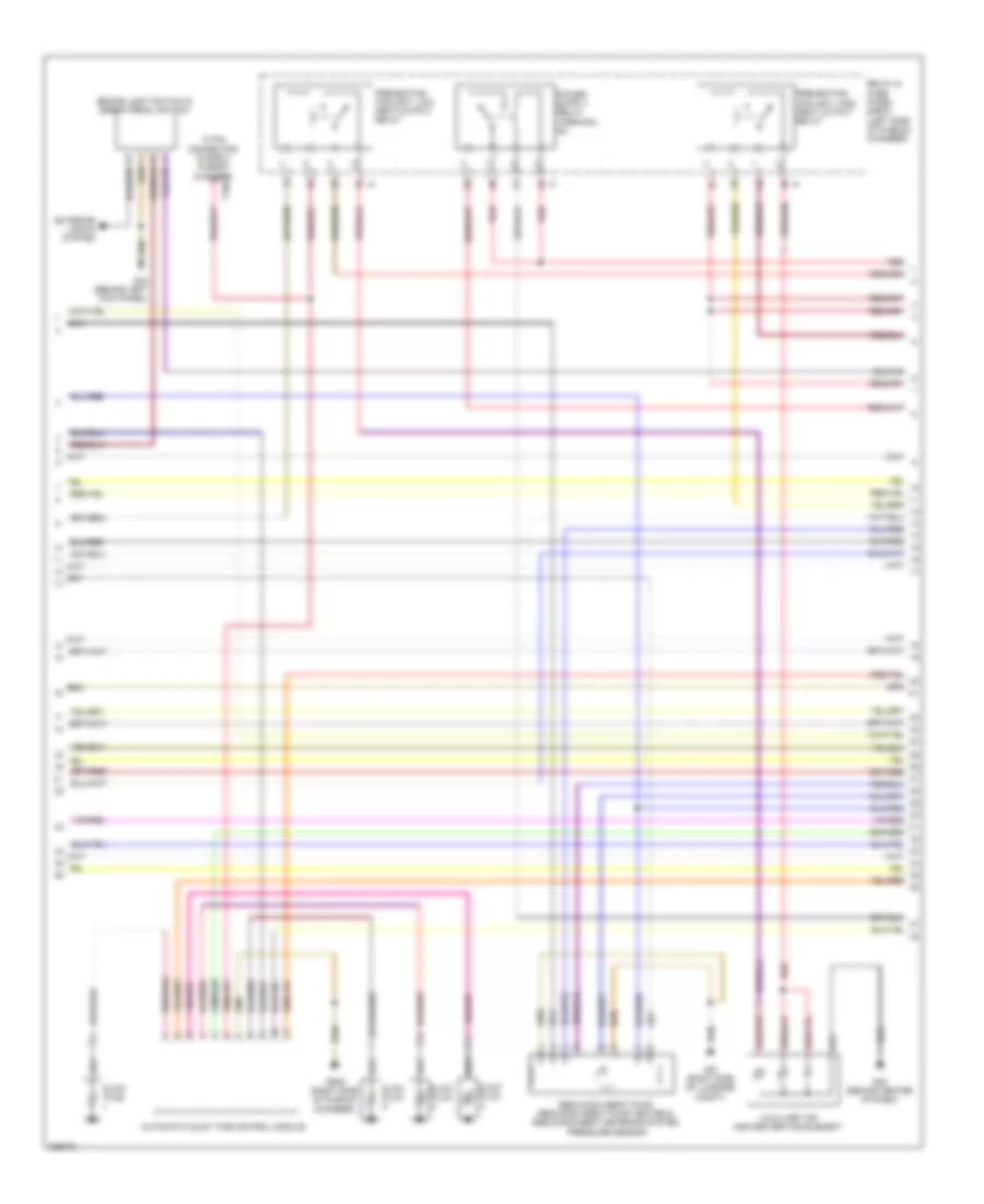
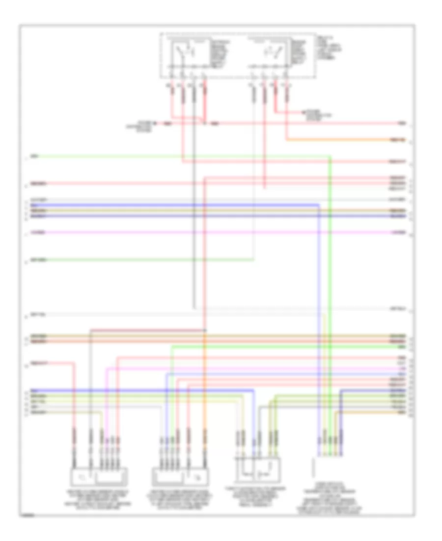
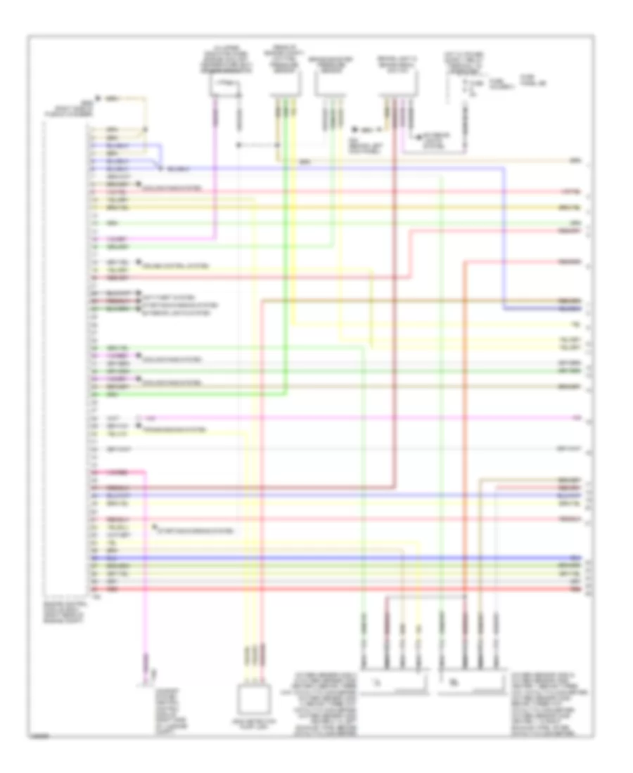
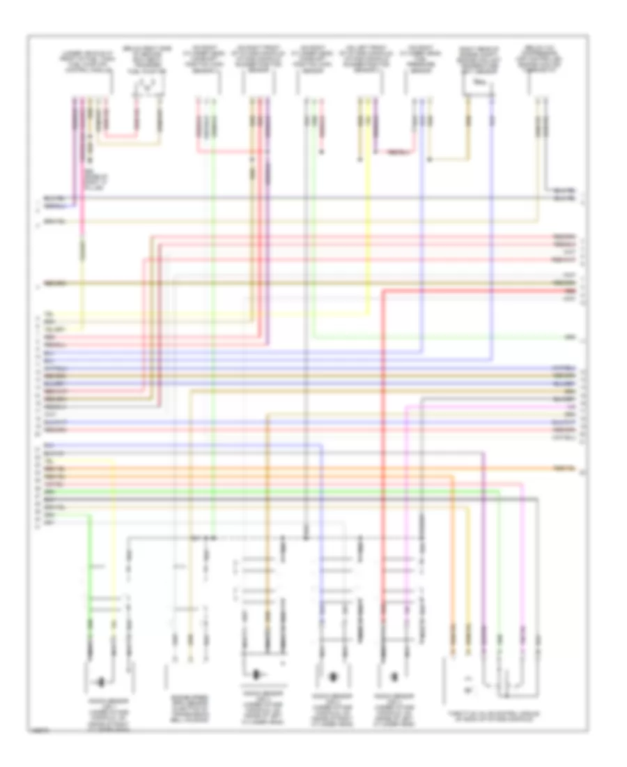
3.0L Turbo, Engine Performance Wiring Diagram (1 of 8) for Audi Q7 4.2 2010

List of elements for 3.0L Turbo, Engine Performance Wiring Diagram (1 of 8) for Audi Q7 4.2 2010:
- (downstream of catalyst) exhaust gas temperature (egt) sensor 3
- (downstream of particle filter) exhaust gas temperature (egt) sensor 4
- (on turbocharger) exhaust gas temperature (egt) sensor 1
- (top center of engine) egr temperature sensor
- Access/ start control module (integral to steering column lock actuator)
- Computer
- Cooling fans system
- Data lines system
- Differential pressure sensor & exhaust pressure sensor 1 (usa) (exhaust pressure sensor 1: upstream of particle filter)
- Engine control module (ecm) (right rear of engine compt)
- Exterior light system
- G609 (right side of plenum chamber)
- Mass air flow (maf) sensor (right side of engine compt)
- Multi-function transmission range (tr) switch
- Red
- Starting/charging system
- T10p
- T20e
- T94
- Throttle position (tp) sensor & accelerator pedal position sensor 2 (in accelerator pedal assembly)
- Turbocharger (tc) control module (at turbocharger)
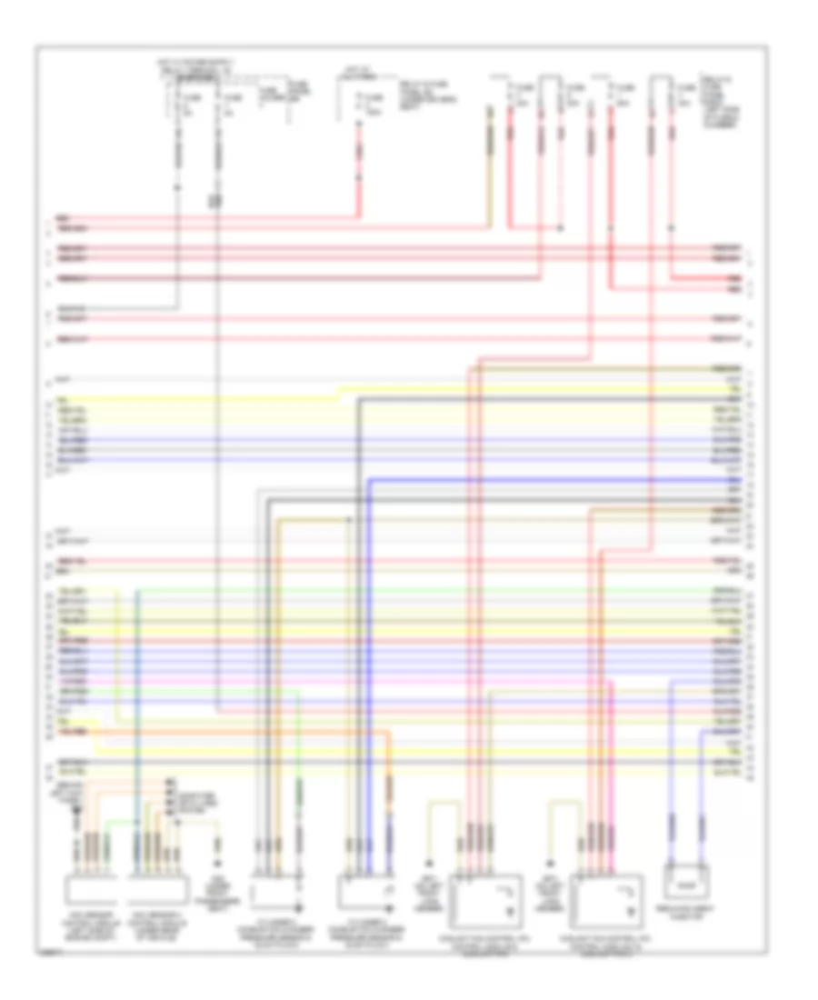
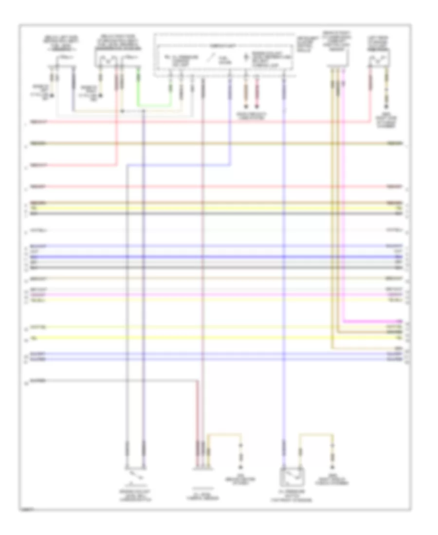
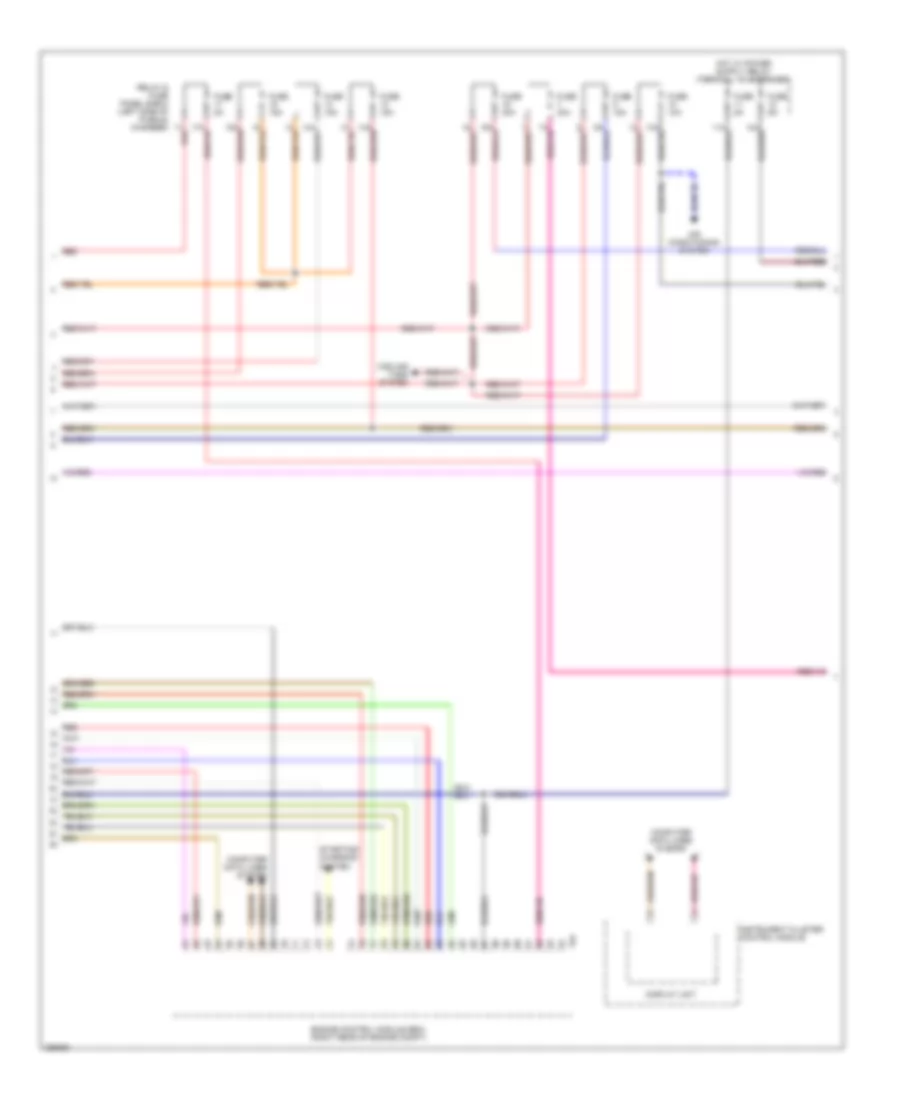
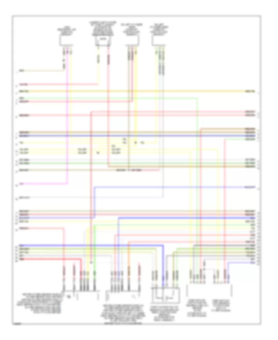
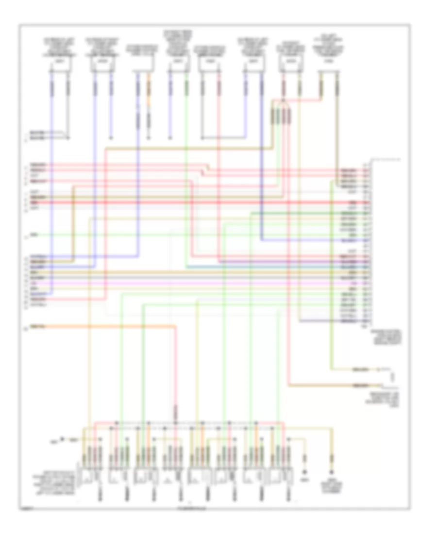
3.0L Turbo, Engine Performance Wiring Diagram (2 of 8) for Audi Q7 4.2 2010
List of elements for 3.0L Turbo, Engine Performance Wiring Diagram (2 of 8) for Audi Q7 4.2 2010:
- 10 pin connector in e-box plenum chamber
- Automatic glow time control module
- Auxiliary air heater heating element
- Brake light switch & break pedal switch
- Exterior lights system
- G44 (behind left kick panel)
- G45 (behind center of dash)
- G51 (right side of luggage compt)
- G609 (right side of plenum chamber)
- Glow plug
- Preheating coolant, high heat output relay
- Preheating coolant, low heat output relay
- Red
- Reducing agent pump, reducing agent pump heater & reducing agent metering system pressure sensor
- Relay & fuse panel e-box (left side of plenum chamber)
- T10e
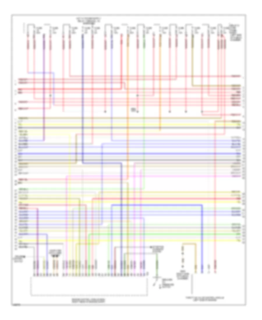
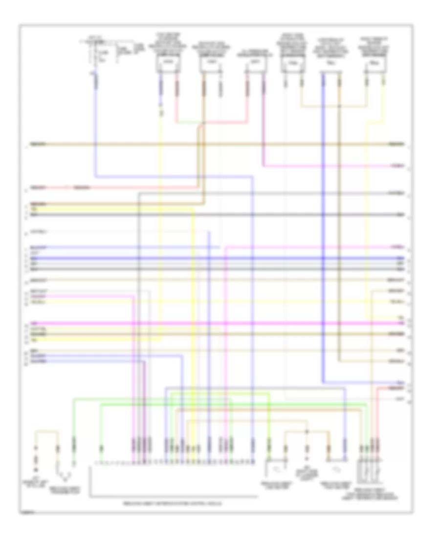
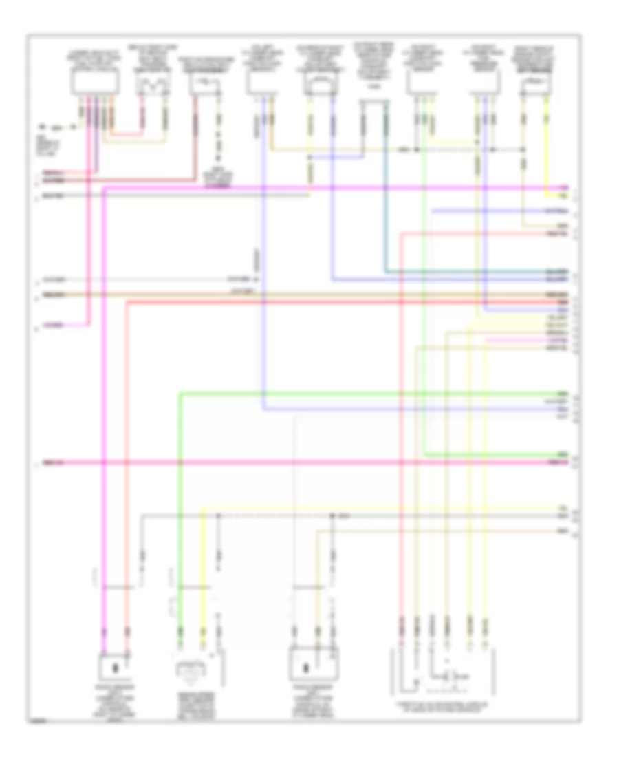
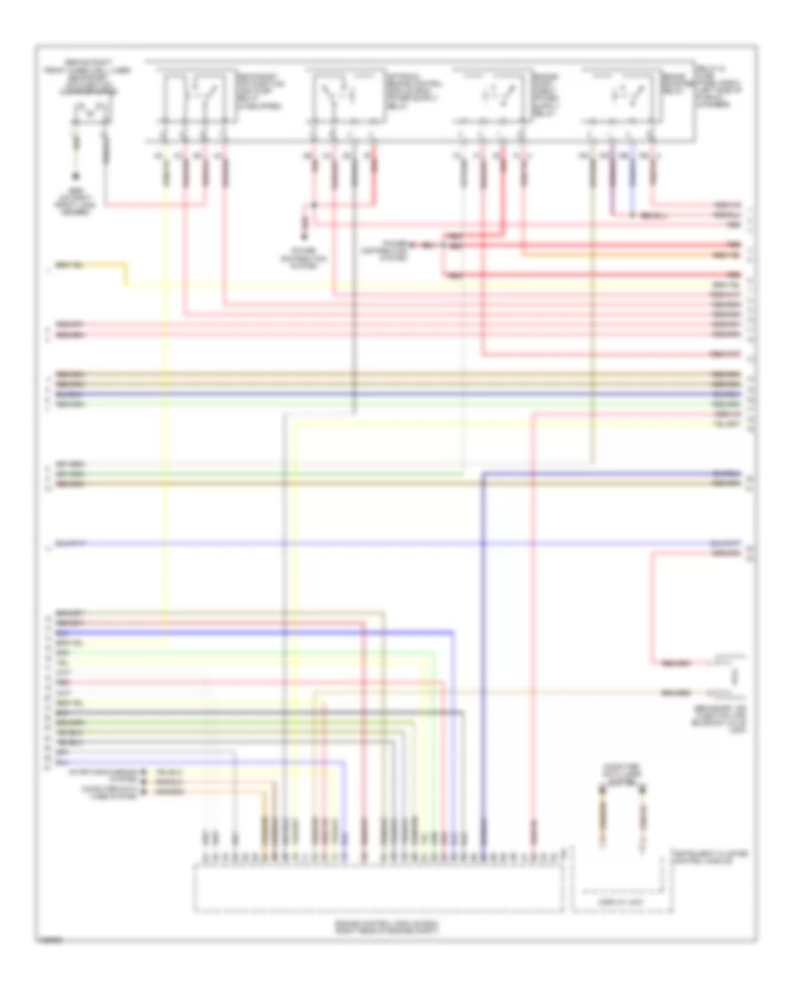
3.0L Turbo, Engine Performance Wiring Diagram (3 of 8) for Audi Q7 4.2 2010
List of elements for 3.0L Turbo, Engine Performance Wiring Diagram (3 of 8) for Audi Q7 4.2 2010:
- (behind left kick panel) g44
- Computer data lines system
- Coolant fan control (fc) control module & coolant fan
- Coolant fan control (fc) control module 2 & coolant fan 2
- Cylinder 2 combustion chamber pressure sensor & glow plug 2
- Cylinder 5 combustion chamber pressure sensor & glow plug 5
- Fuse 150a
- Fuse 40a
- Fuse 5a
- Fuse 60a
- Fuse 80a
- Fuse holder
- Fuse panel sb
- G35 (under front passenger's seat)
- G671 (on left front long member)
- Hot at all times
- Injector
- Nox sensor 2 control module (under rear of vehicle)
- Nox sensor control module (left side of engine compt)
- Red
- Reducing agent
- Relay & fuse panel e-box (left side of plenum chamber)
- Relay & fuse panel sd (under driver's seat)
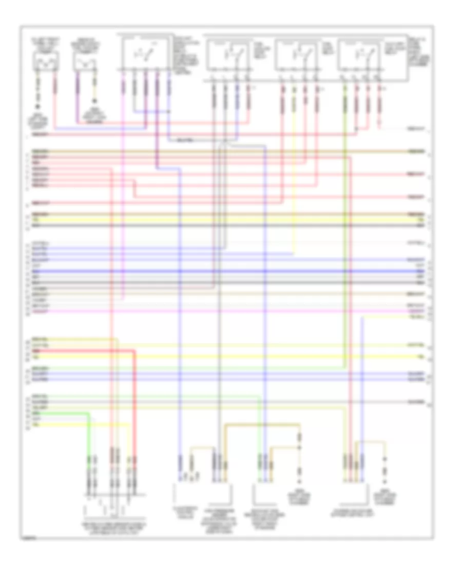
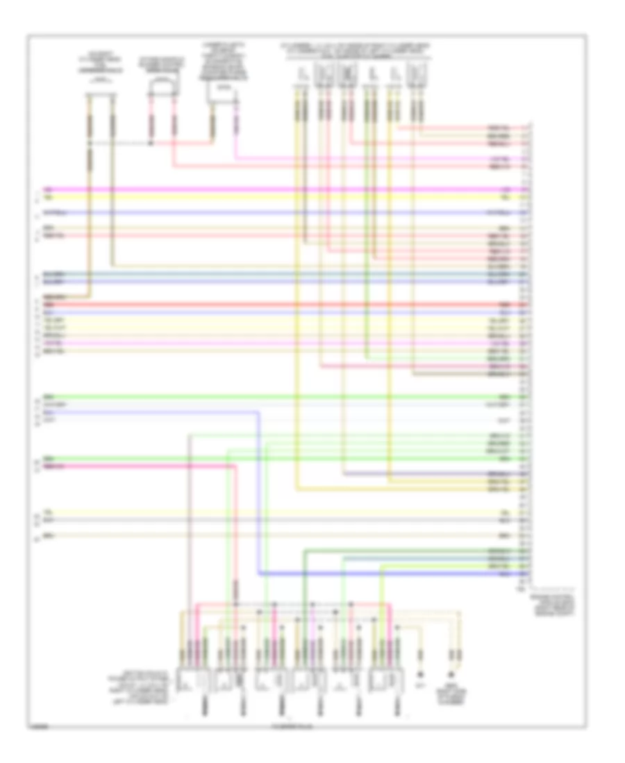
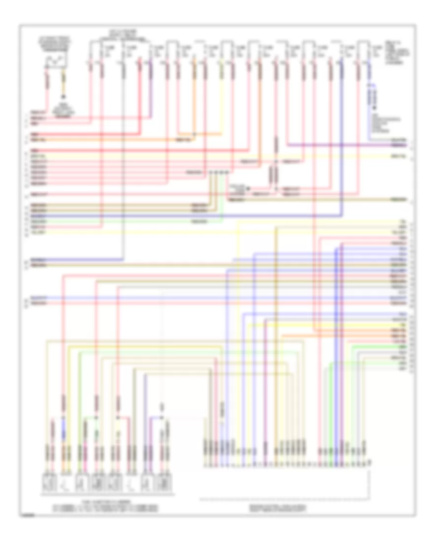
3.0L Turbo, Engine Performance Wiring Diagram (4 of 8) for Audi Q7 4.2 2010
List of elements for 3.0L Turbo, Engine Performance Wiring Diagram (4 of 8) for Audi Q7 4.2 2010:
- 10a
- 11a
- 12a
- 13a
- 14a
- 15a
- 16a
- 17a
- 18a
- Computer data lines system
- Cruise control switch
- Engine control module (ecm) (right rear of engine compt)
- Fuse 10a
- Fuse 15a
- Fuse 20a
- Fuse 5a
- Fuse 80a
- G609 (right side of plenum chamber)
- Red
- Reduced oil pressure switch
- Relay & fuse panel e-box (left side of plenum chamber)
- Starting/ charging system
- T94
- Throttle valve control module (left side of engine)
3.0L Turbo, Engine Performance Wiring Diagram (5 of 8) for Audi Q7 4.2 2010
List of elements for 3.0L Turbo, Engine Performance Wiring Diagram (5 of 8) for Audi Q7 4.2 2010:
- (in left front wheel well)
- (rear of engine compt) fuel cooler pump
- 19a
- 19c
- 19d
- 19e
- 20a
- 20b
- 20c
- 20d
- Auxiliary fuel pump relay
- Charge air cooler bypass control unit
- Climatronic control module
- Coolant circulation pump relay (in relay & fuse panel/ instrument panel center)
- Coolant pump
- Exhaust gas recirculation (egr) cooler pump (right front of engine)
- Fuel cooling pump relay
- Fuel pump relay
- G609 (right side of plenum chamber)
- G640 (left side of engine compt)
- G685 (on right front long member)
- Heated oxygen sensor (ho2s) & oxygen sensor (o2s) heater (upstream of catalyst)
- High pressure sensor (on evaporator expansion valve, under right side of dash)
- Nca
- Red
- Relay & fuse panel e-box (left side of plenum chamber)
- T16c
- T16d
3.0L Turbo, Engine Performance Wiring Diagram (6 of 8) for Audi Q7 4.2 2010
List of elements for 3.0L Turbo, Engine Performance Wiring Diagram (6 of 8) for Audi Q7 4.2 2010:
- (base of left "c" pillar) g61
- (base of right "c" pillar) g62
- (below left side second row seat) fuel level sensor 2
- (below right side of second row seat) fuel level sender & transfer fuel pump (fp)
- (left rear of engine) auxiliary fuel pump
- (rear of right cylinder bank) camshaft position (cmp) sensor
- Computer data lines system
- Display unit
- Engine coolant
- Engine coolant level/temperature (ecl/ect) warning lamp
- Fuel gauge
- G45 (behind center of dash)
- G609 (right side of plenum chamber)
- Instrument cluster control module
- Level (ecl) warning switch
- Oil level thermal sensor
- Oil pressure
- Oil pressure warning ind lamp
- Switch (top front of engine)
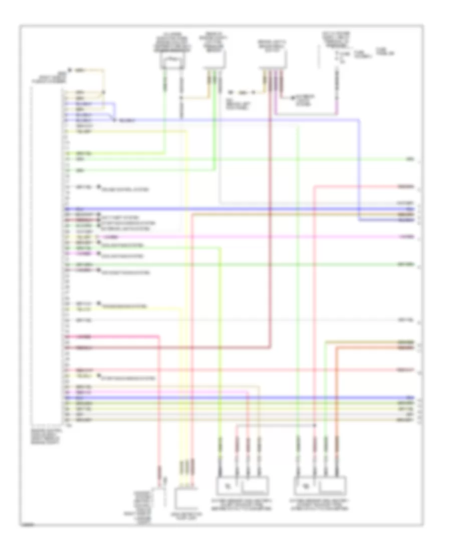
3.0L Turbo, Engine Performance Wiring Diagram (7 of 8) for Audi Q7 4.2 2010
List of elements for 3.0L Turbo, Engine Performance Wiring Diagram (7 of 8) for Audi Q7 4.2 2010:
- (right rear of engine) engine coolant temperature (ect) sensor
- (right side of radiator) engine coolant temperature (ect) sensor (on radiator)
- (top center of engine) exhaust gas recirculation (egr) cooler switch over valve
- (upstream of catalyst) bank 1 exhaust gas temperature (egt) sensor 2
- Exhaust gas recirculation (egr) cooler switch over valve 2
- Fuse 30a
- Fuse holder
- Fuse panel sf
- G51 (right side of luggage compt)
- G77 (base of left "b" pillar)
- Hot at all times
- Oil pressure regulation valve
- Reducing agent line heater
- Reducing agent metering system control module
- Reducing agent tank heater
- Reducing agent tank sensor & reducing agent temperature sensor
- Reducing agent transfer pump
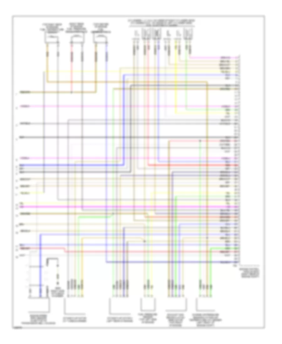
3.0L Turbo, Engine Performance Wiring Diagram (8 of 8) for Audi Q7 4.2 2010
List of elements for 3.0L Turbo, Engine Performance Wiring Diagram (8 of 8) for Audi Q7 4.2 2010:
- (cylinders 1, 2, 3 & 4: on inside of right cylinder head) (cylinders 5 & 6 : on inside of left cylinder head) fuel injector cylinders
- (right rear of engine) fuel pressure regulator valve
- (top center of engine) fuel metering valve
- (top right rear of engine) fuel temperature sensor
- Charge air pressure sensor & intake air temperature (iat) sensor (left front of engine compt)
- Engine control module (ecm) (right rear of engine compt)
- Engine speed (rpm) sensor (in bottom of transmission bell housing)
- Exhaust gas recirculation (egr) motor (top front of engine)
- Fuel pressure sensor (top left side of engine)
- G609 (right side of plenum chamber)
- Intake flap motor (at turbocharger)
- Intake flap motor 2 (left rear of engine)
- Red
- T60
3.6L
3.6L, Engine Performance Wiring Diagram (1 of 5) for Audi Q7 4.2 2010
List of elements for 3.6L, Engine Performance Wiring Diagram (1 of 5) for Audi Q7 4.2 2010:
- (in upper radiator hose) engine coolant temperature (ect) sensor (radiator)
- (rear of engine compt) low fuel pressure sensor
- Air conditioning system
- Anti-theft system
- Brake light & brake pedal switch
- Comfort system central control module (right side of luggage compt)
- Cooling fans system
- Cruise control system
- Engine control module (ecm) (right rear of engine compt)
- Exterior lights system
- Fuse 5a
- Fuse holder 3
- Fuse panel sb
- G44 (behind left kick panel)
- G609 (right side of plenum chamber)
- Leak detection pump (ldp)
- Nca
- Oxygen sensor (o2s) heater 1 (in right exhaust pipe, after catalytic converter)
- Oxygen sensor (o2s) heater 2 (in left exhaust pipe, before catalytic converter)
- Starting/charging system
- T10g
- T94
- Transmissions system
3.6L, Engine Performance Wiring Diagram (2 of 5) for Audi Q7 4.2 2010
List of elements for 3.6L, Engine Performance Wiring Diagram (2 of 5) for Audi Q7 4.2 2010:
- 1b red
- 1h a
- 2b red
- 2f red
- Heated oxygen sensor (ho2s) & oxygen sensor (o2s) heater (oxygen sensor (o2s) heater: in right exhaust, before catalytic converter)
- Heated oxygen sensor (ho2s) 2 & oxygen sensor (o2s) heater 2 (oxygen sensor (o2s) heater 2: in left exhaust pipe, before catalytic converter)
- Mass air flow (maf)/intake air temperature (iat) sensor (intake air temperature (iat) sensor: left front of engine compt) (mass air flow(maf) sensor: in air intake duct at filter housing)
- Nca
- Power distribution system
- Red
- Relay & fuse panel e-box (left side of plenum chamber)
- Throttle position (tp) sensor & accelerator pedal position (app) sensor 2 (in accelerator pedal assembly)
3.6L, Engine Performance Wiring Diagram (3 of 5) for Audi Q7 4.2 2010
List of elements for 3.6L, Engine Performance Wiring Diagram (3 of 5) for Audi Q7 4.2 2010:
- Air conditioning system
- Computer data lines system
- Cooling fans system
- Display unit
- Engine control module (ecm) (right rear of engine compt)
- Fuse 10a
- Fuse 15a
- Fuse 30a
- Fuse 5a
- Instrument cluster control module
- Red
- Relay & fuse panel e-box (left side of plenum chamber)
- Starting/ charging system
- T94
3.6L, Engine Performance Wiring Diagram (4 of 5) for Audi Q7 4.2 2010
List of elements for 3.6L, Engine Performance Wiring Diagram (4 of 5) for Audi Q7 4.2 2010:
- (below right side of second row seat) transfer fuel pump (fp)
- (on left cylinder head) camshaft position (cmp) sensor 2
- (on rear of right cylinder head) camshaft adjustment valve 1 (exhaust)
- (on right cylinder head) camshaft position (cmp) sensor
- (on right cylinder head) fuel pressure sensor
- (on right rear cylinder head near intake manifold) camshaft adjustment valve 1
- (right rear of engine compt) engine coolant temperature (ect) sensor
- (under vehicle at front of fuel tank) fuel pump (fp) control module
- Engine speed (rpm) sensor (in bottom of transmission bell housing)
- G609 (right side of plenum chamber)
- G62 (base of right "c" pillar)
- Knock sensor (ks) 1 (under intake manifold, on inside of right cylinder head)
- Knock sensor (ks) 2 (under intake manifold, on inside of right cylinder head)
- Positive crankcase ventilation (pcv) heating element
- Red
- Throttle valve control module (at back of intake manifold)
3.6L, Engine Performance Wiring Diagram (5 of 5) for Audi Q7 4.2 2010
List of elements for 3.6L, Engine Performance Wiring Diagram (5 of 5) for Audi Q7 4.2 2010:
- (cylinders 1, 2, 3 & 4: on inside of right cylinder head) (cylinders 5 & 6 : on inside of left cylinder head) fuel injector cylinders
- (on right cylinder head) fuel metering valve
- (under plastic cover by throttle body) evaporative emission (evap) canister purge regulator valve
- Engine control module (ecm) (right rear of engine compt)
- G17
- G609 (right side of plenum chamber)
- Ignition coils w/ power output stage (coils 1, 2, 3 & 4: on right cylinder head) (coils 5 & 6: on left cylinder head)
- Intake manifold runner control (imrc) valve
- Nca
- Red
- T60
- To spark plug
4.2L
4.2L, Engine Performance Wiring Diagram (1 of 6) for Audi Q7 4.2 2010
List of elements for 4.2L, Engine Performance Wiring Diagram (1 of 6) for Audi Q7 4.2 2010:
- (in upper radiator hose) engine coolant temperature (ect) sensor (radiator)
- (rear of engine compt) low fuel pressure sensor
- Anti-theft system
- Brake booster pressure sensor
- Brake light & brake pedal switch
- Comfort system central control module (right side of luggage compt)
- Cooling fans system
- Cruise control system
- Engine control module (ecm) (right rear of engine compt)
- Exterior lights system
- Fuse 5a
- Fuse holder 3
- Fuse panel sb
- G44 (behind left kick panel)
- G609 (right side of plenum chamber)
- Leak detection pump (ldp)
- Nca
- Oxygen sensor (o2s) & oxygen sensor (o2s) heater 1 (behind three way catalytic converter) (oxygen sensor (o2s): behind three way catalytic converter) (oxygen sensor (o2s) heater 1: in right exhaust pipe, after catalytic converter)
- Oxygen sensor (o2s) 2 & oxygen sensor (o2s) heater 2 (behind three way catalytic converter) (oxygen sensor (o2s) 2: behind three way catalytic converter) (oxygen sensor (o2s) heater 2: in left exhaust pipe, before catalytic converter)
- Red
- Starting/charging system
- T10g
- T94
- Transmissions system
4.2L, Engine Performance Wiring Diagram (2 of 6) for Audi Q7 4.2 2010
List of elements for 4.2L, Engine Performance Wiring Diagram (2 of 6) for Audi Q7 4.2 2010:
- (on left cylinder head) camshaft position (cmp) sensor 2
- (on left cylinder head) camshaft position (cmp) sensor 4
- (under plastic cover by throttle body) evaporative emission (evap) canister purge regulator valve
- (usa) secondary air injection sensor 1
- Heated oxygen sensor (ho2s) & oxygen sensor (o2s) heater (heated oxygen sensor (ho2s) 2: in exhaust pipe for right cylinder head, before catalytic converter) (oxygen sensor (o2s) heater: in right exhaust before catalytic converter)
- Heated oxygen sensor (ho2s) 2 & oxygen sensor (o2s) heater 2 (heated oxygen sensor (ho2s) 2: in exhaust pipe for left cylinder head, before catalytic converter) (oxygen sensor (o2s) heater 2: in left exhaust pipe, before catalytic converter)
- Mass air flow (maf) sensor 2 (in air intake duct at filter housing)
- Mass air flow (maf)/intake air temperature (iat) sensor (in air intake duct at filter housing)
- Nca
- Red
- Throttle position (tp) sensor & accelerator pedal position (app) sensor 2 (in accelerator pedal assembly)
4.2L, Engine Performance Wiring Diagram (3 of 6) for Audi Q7 4.2 2010
List of elements for 4.2L, Engine Performance Wiring Diagram (3 of 6) for Audi Q7 4.2 2010:
- (behind right front wheelwell liner) secondary air injection (air) pump motor
- 19d c
- 1b red
- 1h a
- 2b red
- 2f red
- Brake booster relay
- Computer data lines system
- Display unit
- Engine control module (ecm) (right rear of engine compt)
- G685 (on right front long member)
- Instrument cluster control module
- Power distribution system
- Red
- Relay & fuse panel e-box (left side of plenum chamber)
- Secondary air injection (air) pump relay (if equipped)
- Secondary air injection (air) solenoid valve (usa)
- Starting/charging system
- T94
4.2L, Engine Performance Wiring Diagram (4 of 6) for Audi Q7 4.2 2010
List of elements for 4.2L, Engine Performance Wiring Diagram (4 of 6) for Audi Q7 4.2 2010:
- (at right front of engine compt) brake system vacuum pump
- Air conditioning & cooling fans systems
- Cooling fans system
- Engine control module (ecm) (right rear of engine compt)
- Fuel injector cylinders (cylinders 1, 2, 3 & 4: on inside of right cylinder head) (cylinders 5 , 6, 7 & 8 : on inside of left cylinder head)
- Fuse 10a
- Fuse 15a
- Fuse 30a
- Fuse 50a
- Fuse 5a
- G685 (on right front long member)
- Red
- Relay & fuse panel e-box (left side of plenum chamber)
- T60
4.2L, Engine Performance Wiring Diagram (5 of 6) for Audi Q7 4.2 2010
List of elements for 4.2L, Engine Performance Wiring Diagram (5 of 6) for Audi Q7 4.2 2010:
- (below a/c compressor) map controlled engine cooling thermostat
- (below right side of second row seat) transfer fuel pump (fp)
- (on left front of intake manifold) intake manifold runner position sensor 2
- (on right cylinder head) camshaft position (cmp) sensor
- (on right cylinder head) camshaft position (cmp) sensor 3
- (on right cylinder head) fuel pressure sensor
- (on right front of intake manifold) intake manifold runner position sensor
- (right rear of engine compt) engine coolant temperature (ect) sensor
- (under vehicle at front of fuel tank) fuel pump (fp) control module
- Engine speed (rpm) sensor (in bottom of transmission bell housing)
- G62 (base of right "c" pillar)
- Knock sensor (ks) 1 (under intake manifold, on inside of right cylinder head)
- Knock sensor (ks) 2 (under intake manifold, on inside of right cylinder head)
- Knock sensor (ks) 3 (under intake manifold, on inside of left cylinder head)
- Knock sensor (ks) 4 (under intake manifold, on inside of left cylinder head)
- Nca
- Red
- Throttle valve control module (at back of intake manifold)
4.2L, Engine Performance Wiring Diagram (6 of 6) for Audi Q7 4.2 2010
List of elements for 4.2L, Engine Performance Wiring Diagram (6 of 6) for Audi Q7 4.2 2010:
- (on left cylinder head, in high pressure pump) fuel metering valve 2
- (on rear of left cylinder head) camshaft adjustment valve 2
- (on rear of left cylinder head) camshaft adjustment valve 2 (exhaust)
- (on rear of right cylinder head) camshaft adjustment valve 1 (exhaust)
- (on right cylinder head) fuel metering valve
- (on right rear cylinder head near intake manifold) camshaft adjustment valve 1
- Engine control module (ecm) (right rear of engine compt)
- G600
- G601
- G609 (right side of plenum chamber)
- Ignition coils w/ power output stage (coils 1, 2, 3 & 4: on right cylinder head) (coils 5, 6, 7 & 8: on left cylinder head)
- Intake manifold runner control (imrc) valve
- Intake manifold runner control (imrc) valve 2
- Nca
- Red
- Secondary air injection (air) solenoid valve 2 (usa)
- T60
- To spark plug