ENGINE PERFORMANCE
4.2L
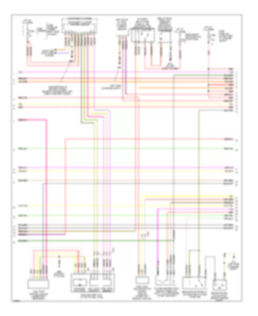
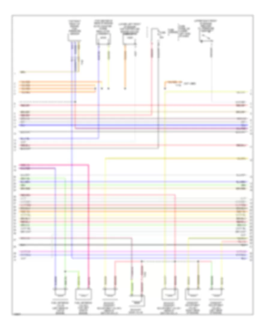
4.2L, Engine Performance Wiring Diagram (1 of 7) for Audi RS 5 Prestige 2013

List of elements for 4.2L, Engine Performance Wiring Diagram (1 of 7) for Audi RS 5 Prestige 2013:
- (left side of engine compt) g12
- (on brake pedal assembly) brake lamp switch
- 12a
- Climatronic control module
- Comfort system central control module (right rear of luggage compt)
- Coolant recirculation pump
- Cooling fans system
- Cruise control system
- Engine control module (ecm) (in left plenum chamber)
- Fuse 5a
- Fuse carrier
- G12 (left side of engine compt)
- G687 (convertible: on center tunnel) (except convertible: left side of center tunnel)
- Heated oxygen sensor (in right exhaust)
- Heated oxygen sensor 2 (in left exhaust)
- Hot at all times
- Manifold absolute pressure sensor & intake air temperature sensor
- Nca
- Oxygen sensor (o2s) behind 3-way catalytic converter (in right exhaust)
- Red
- Relay/fuse panel f (right side of luggage compt)
- Relay/fuse panel sb (in left plenum chamber e-box)
- Starting/charging system
- T17e
- T17q
- T17r
- T20e
- T32d
- T91
- Transmissions system
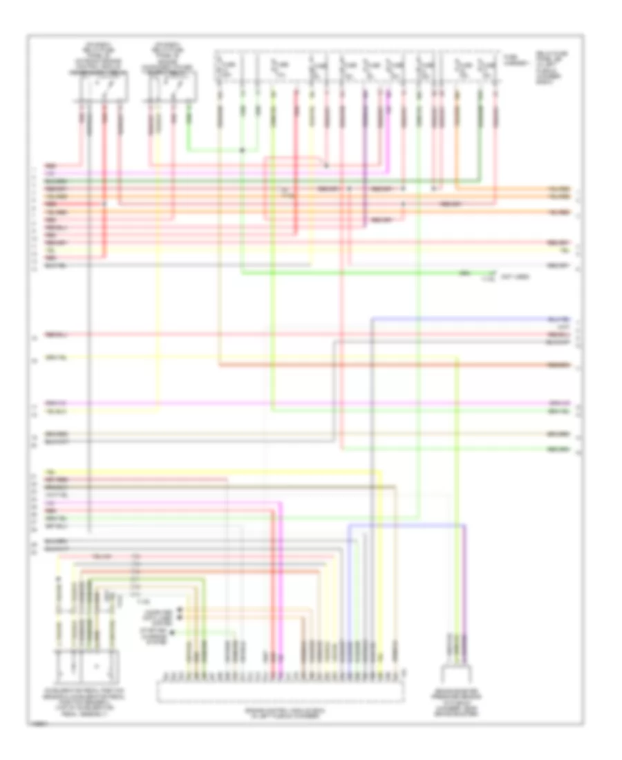
4.2L, Engine Performance Wiring Diagram (2 of 7) for Audi RS 5 Prestige 2013
List of elements for 4.2L, Engine Performance Wiring Diagram (2 of 7) for Audi RS 5 Prestige 2013:
- (below right headlight assembly) secondary air injection pump motor
- (bottom of oil pan) oil level thermal sensor
- (convertible: on center tunnel) (except convertible: left side of center tunnel)
- (left side of engine compt)
- (on e-box
- 50a
- Brake booster relay (on e-box relay/fuse panel sb)
- Brake system vacuum pump (rear of engine compt)
- Computer data lines system
- Fuel delivery unit (in top of fuel tank)
- Fuel level sensor
- Fuel level sensor 2
- Fuel pump control module (under right rear seat)
- Fuel tank leak detection control module (under left rear of vehicle)
- Fuse 110a
- Fuse 5a
- Fuse carrier
- Fuse panel sa (on battery, in luggage compt)
- Fuse panel sd (under right side of dash)
- G12
- G12 (left side of engine compt)
- G615 (on left strut tower)
- G663 (on right "c" pillar)
- G687
- Hot at all times
- Instrument cluster
- Instrument cluster control module
- Nca
- Oxygen sensor (o2s) 2 behind three way catalytic converter (in left exhaust)
- Red
- Relay/fuse panel b - sb) secondary air injection pump relay
- Secondary air injection pump fuse
- T17g
- T17q
- T4s
- T6r
- Transfer fuel pump
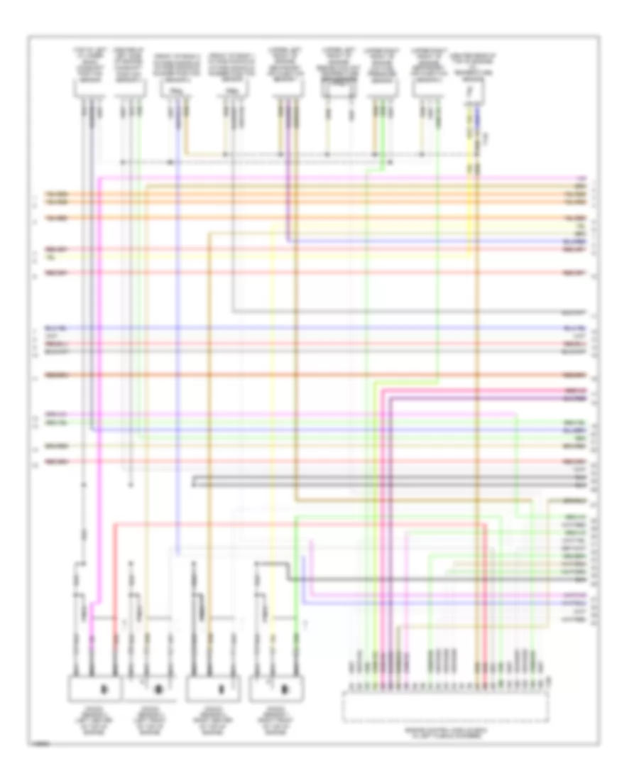
4.2L, Engine Performance Wiring Diagram (3 of 7) for Audi RS 5 Prestige 2013
List of elements for 4.2L, Engine Performance Wiring Diagram (3 of 7) for Audi RS 5 Prestige 2013:
- (not used)
- 10a
- 14a
- 16a
- 17a
- Accelerator pedal position sensor & accelerator pedal position sender 2 (top of accelerator pedal assembly)
- Brake booster pressure sensor (in plenum chamber, near brake booster)
- Computer data lines system
- Engine control module (ecm) (in left plenum chamber)
- Fuse 10a
- Fuse 15a
- Fuse 30a
- Fuse 5a
- Fuse carrier 1
- Red
- Relay/fuse panel sb (in left plenum chamber e-box)
- Starting/ charging system
- T17e
- T17q
- T17r
- T91
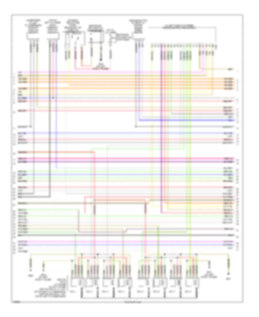
4.2L, Engine Performance Wiring Diagram (4 of 7) for Audi RS 5 Prestige 2013
List of elements for 4.2L, Engine Performance Wiring Diagram (4 of 7) for Audi RS 5 Prestige 2013:
- (center of left side of engine)
- (center rear of top of engine) oil temperature sensor
- (front of bank 1 intake manifold) intake manifold runner position sensor
- (front of bank 2 intake manifold) intake manifold runner position sensor 2
- (top of left cylinder bank) camshaft position sensor
- (upper left front of engine) engine coolant temperature (ect) sensor
- (upper left front of engine) secondary air injection sensor 1
- (upper right front of engine) low fuel pressure sensor
- (upper right front of engine) secondary air injection sensor 2
- Camshaft position sensor 4
- Engine control module (ecm) (in left plenum chamber)
- Knock sensor 1 (right front of top of engine)
- Knock sensor 2 (right center of top of engine)
- Knock sensor 3 (left front of top of engine)
- Knock sensor 4 (left center of top of engine)
- Nca
- Red
- T105
- T14d
4.2L, Engine Performance Wiring Diagram (5 of 7) for Audi RS 5 Prestige 2013
List of elements for 4.2L, Engine Performance Wiring Diagram (5 of 7) for Audi RS 5 Prestige 2013:
- (center bottom of front of engine) engine speed sensor
- (in left plenum chamber) engine control module (ecm)
- (on e-box relay/fuse panel) secondary air injection pump relay 2
- (top of left cylinder bank) camshaft position sensor 2
- (under rear of left cylinder bank) camshaft position sensor 3
- 50a
- Coil 1
- Coil 2
- Coil 3
- Coil 4
- Coil 5
- Coil 6
- Coil 7
- Coil 8
- G600
- G601
- G615 (on left strut tower)
- Hot at all times
- Ignition coils (w/ power output stage) (ignition coils 1, 2, 3 & 4: top of right cylinder bank) (ignition coils 5, 6, 7 & 8: top of left cylinder bank)
- Nca
- Secondary air injection pump fuse 2
- Secondary air injection pump motor 2
- T105
- To spark plug
4.2L, Engine Performance Wiring Diagram (6 of 7) for Audi RS 5 Prestige 2013
List of elements for 4.2L, Engine Performance Wiring Diagram (6 of 7) for Audi RS 5 Prestige 2013:
- (left rear of top of engine)
- (lower left front of engine) map controlled engine cooling thermostat
- (not used)
- (top center of rear of engine)
- (top right front of engine) fuel pressure sensor
- (upper right front of engine) reduced oil pressure switch
- Camshaft adjustment valve 1 (right rear of engine)
- Camshaft adjustment valve 2 (left rear of engine)
- Evap canister purge regulator valve 1
- Exhaust camshaft adjustment valve 1 (rear of ignition coil 4)
- Exhaust camshaft adjustment valve 2 (rear of ignition coil 8)
- Exhaust door valve
- Fuel metering valve
- Fuel metering valve 2 (top left side of engine)
- Fuse 25a
- Fuse carrier
- Fuse panel sc (under left side of dash)
- T14c
- T17q
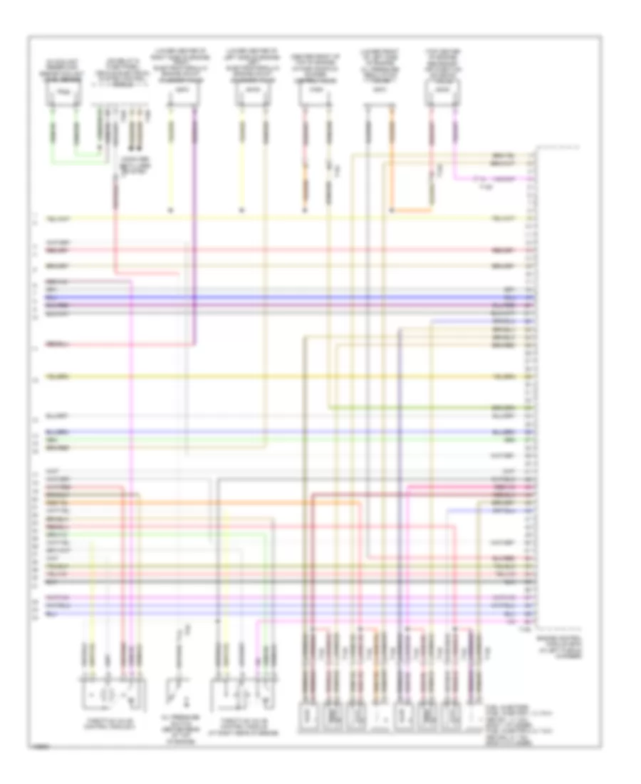
4.2L, Engine Performance Wiring Diagram (7 of 7) for Audi RS 5 Prestige 2013
List of elements for 4.2L, Engine Performance Wiring Diagram (7 of 7) for Audi RS 5 Prestige 2013:
- (center front of top of engine) intake manifold runner control valve
- (in coolant reservoir) engine coolant level sensor
- (lower center of left side of engine) left electrohydraulic engine mount solenoid valve
- (lower center of right side of engine) right electrohydraulic engine mount solenoid valve
- (lower front of left side of engine) oil pressure regulation valve
- (on relay & fuse panel) vehicle electrical system control module
- (top center of engine) secondary air injection solenoid valve
- Bank 1 cylinder) (fuel injector 5, 6, 7 & 8: above 5, 6, 7 & 8 bank 2 cylinder)
- Computer data lines system
- Engine control module (ecm) (in left plenum chamber)
- Fuel injectors (fuel injector 1, 2, 3 & 4: above 1, 2, 3 & 4
- Oil pressure switch (center rear of top of engine)
- T105
- T14c
- T14d
- T16b
- T17q
- T32b
- Throttle valve control module (at right rear of engine)
- Throttle valve control module 2