ENGINE PERFORMANCE
1.8L
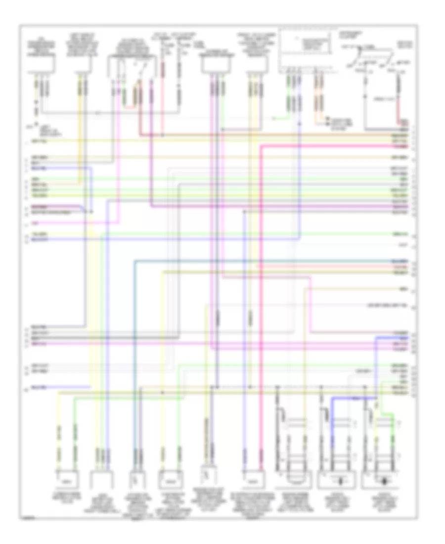
1.8L, Engine Performance Wiring Diagram (1 of 3) for Audi TT Quattro 2002

List of elements for 1.8L, Engine Performance Wiring Diagram (1 of 3) for Audi TT Quattro 2002:
- (left of eng compt) g12
- (pins 15-20 not used)
- (pins 20 & 23-24 not used)
- A/c system
- Accelerator pedal position sender 2/ throttle position (tp) sensor (above accelerator pedal)
- Brake- light switch (above brake pedal, on bracket)
- Charging system
- Clutch vacuum vent valve switch (above clutch pedal, on bracket)
- Computer data lines system
- Cruise control system
- Exhaust temperature sensor (w/ amu eng only)
- Fuse 10a
- Fuse 50a
- Fuse 7.5a
- Fuse panel
- G12 (left side of eng compt)
- G12 (left side of engine compt)
- Heated oxygen sensor 1 (on exhaust system, upstream of twc)
- Heated oxygen sensor 2 (on exhaust system, downstream of twc)
- Hot at all times
- Hot in start or run
- Mass airflow (maf) sensor (on air cleaner housing)
- Motronic engine control module (in center plenum, between firewall & base of windshield)
- Nca
- Power steering pressure switch (engine code atc, awp) (on power steering pump, on front of eng)
- Red
- Secondary air injection (air) pump relay
- Secondary air injection pump motor (lower left side of eng, below intake manifold)
- W-box (in engine compartment)
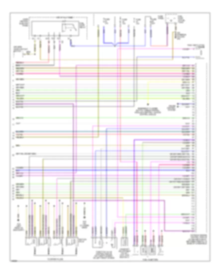
1.8L, Engine Performance Wiring Diagram (2 of 3) for Audi TT Quattro 2002
List of elements for 1.8L, Engine Performance Wiring Diagram (2 of 3) for Audi TT Quattro 2002:
- (from 11/01)
- (front of cylinder head, behind timing belt cover) camshaft position (cmp) sensor 2
- (left front of eng compt)
- (left side of eng, below intake manifold) secondary air injection (air) solenoid valve
- (mil)
- (on transmission) speedometer vehicle speed sensor
- Charge air pressure sensor
- Computer data lines system
- Engine coolant temperature (ect) sensor (rear of cylinder, on coolant outlet)
- Engine speed (rpm) sensor (left side of cylinder block, next to oil filter)
- Evaporative emission (evap) canister purge regulator valve (next to coolant reservoir, on right side of eng compt)
- Fuse 10a
- Fuse 15a
- Fuse panel
- G12
- Hot at all times
- Hot in start or run
- Ignition switch
- Instrument cluster
- Intake air temperature sensor (on intake manifold, near throttle body)
- Knock sensor (ks) 1 (left front of cylinder block)
- Knock sensor (ks) 2 (left rear of cylinder block)
- Leak detection pump (ldp) (inside right front wheelwell)
- Malfunction indicator lamp
- Nca
- Off
- Run
- Start
- T32/28
- T32/3
- T32a/18
- T32a/19
- T32a/28
- Turbocharge recirculating valve
- Wastegate bypass regulator valve (left rear corner of eng compt, on intake duct)
1.8L, Engine Performance Wiring Diagram (3 of 3) for Audi TT Quattro 2002
List of elements for 1.8L, Engine Performance Wiring Diagram (3 of 3) for Audi TT Quattro 2002:
- (on steering column) g42
- 87f
- Camshaft adjustment valve 1 (atc, awd eng only)
- Cruise control system
- Driver's door contact switch
- Emergency flasher switch, airbag control module & central locking control module
- Fuel injectors
- Fuel pump (in fuel tank)
- Fuel pump relay
- Fuse 10a
- Fuse 20a
- Fuse panel
- G12 (left front of eng compt)
- G15 (on cylinder head)
- Hot at all times
- Ignition coils
- Micro central electric panel
- Motronic engine control module (in center plenum, between firewall & base of windshield)
- Nca
- Tank ventilation valve
- Throttle valve control module (on throttle body, on left front of eng)
- To spark plugs