INSTRUMENT CLUSTER
Auto Check System Wiring Diagram for Audi A6 Avant Quattro 2000

List of elements for Auto Check System Wiring Diagram for Audi A6 Avant Quattro 2000:
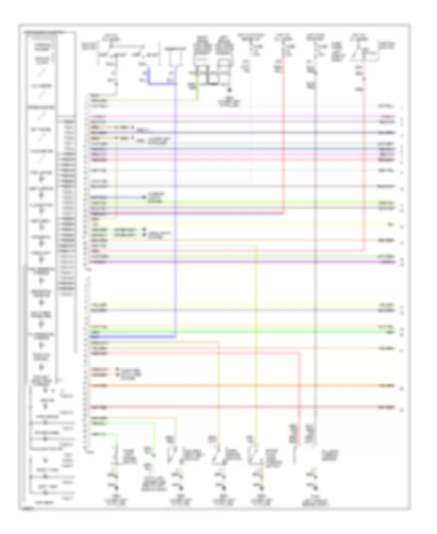
Instrument Cluster Wiring Diagram (1 of 2) for Audi A6 Avant Quattro 2000
List of elements for Instrument Cluster Wiring Diagram (1 of 2) for Audi A6 Avant Quattro 2000:
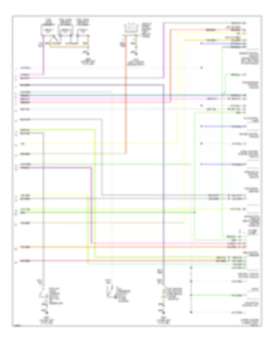
Instrument Cluster Wiring Diagram (2 of 2) for Audi A6 Avant Quattro 2000
List of elements for Instrument Cluster Wiring Diagram (2 of 2) for Audi A6 Avant Quattro 2000: