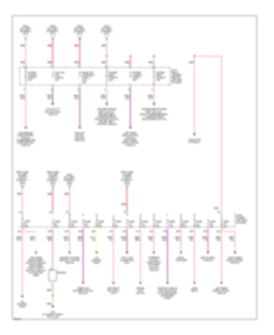
POWER DISTRIBUTION
Power Distribution Wiring Diagram, with Convertible (1 of 2) for Audi A4 2004

List of elements for Power Distribution Wiring Diagram, with Convertible (1 of 2) for Audi A4 2004:
- 10a
- 16a
- 22a
- 243a
- 30a
- 31a
- 33a
- 36a
- 37a
- 38a
- 50b
- 86s
- 9-pin relay carrier (behind left side of dash)
- A/c control head
- A32
- A33
- A34
- A52
- A57
- Abs control module (w/edl)
- Abs control module fuse 1
- Acc
- Acc run
- Air quality sensor, high pressure sensor
- Airbag control module
- Back-up light switch, automatic day/night interior mirror, data link connector (dlc), shift lock solenoid, multi-function transmission range (tr) switch, transmission control module, park/neutral position relay
- Battery
- Brake booster relay
- Brake light switch, clutch vacuum vent valve switch, abs control module (w/ edl), anti-slip control switch
- Cigarette lighter
- Convertible top control module
- Convertible top fuse 40a
- Convertible top operation hydraulic unit
- D50
- Driver side door control module
- E-box relay carrier (left rear of engine compt)
- Fuel pump (fp) relay
- Fuse 10a
- Fuse 150a
- Fuse 15a
- Fuse 25a
- Fuse 30a
- Fuse 40a
- Fuse 50a
- Fuse 5a
- Fuse holder (left end of dash)
- Fuse strip (main fuse)
- G33 (behind right side of dash)
- Garage door opener control head, garage door opener control module
- Generator
- Headlight range control module
- Ignition/starter switch
- Instrument panel
- Instrument panel, steering column electronic systems control module
- Light switch
- Load reduction relay
- Motronic engine control module (ecm)
- Nca
- Off
- Oil level thermal sensor, telephone/telematic control module, board computer function selector switch ii, tiptronic switch, telephone control module for operating electronics, control module for navigation w/ cd-mechanism
- Passenger side airbag off indicator
- Passenger side door control module
- Radar interior monitoring control module, alarm horn, comfort system central control module
- Red
- Red b
- Run
- Secondary air injection (air) pump relay
- Servotronic control module
- Start
- Starter
- Starter, starter locking relay (clutch pedal switch), starter interlock alarm system relay, park/neutral position relay
- Steering column electronic systems control module
- T10b
- T32b
- Telephone amplifier
- Telephone/ telematic control module, telephone control module for operating electronics
- To 4-pin relay carrier (diagram 2 of 2)
- To fuse (diagram 2 of 2)
- To fuse holder (diagram 2 of 2)
- Transmission control module (tcm)
- Vehicle electrical system control module
- Washer nozzle heater (left/right)
Power Distribution Wiring Diagram, with Convertible (2 of 2) for Audi A4 2004
List of elements for Power Distribution Wiring Diagram, with Convertible (2 of 2) for Audi A4 2004:
- 12a
- 13a
- 14a
- 15a
- 24a
- 25a
- 26a
- 35a
- 39a
- 4-pin relay carrier (behind left end of dash)
- 40a
- 42a
- 44a
- A/c control head
- A98
- Abs control module
- Brake light switch
- Comfort system central control module
- Control module for navigation w/ cd mechanism, instrument panel
- Coolant fan fuse 42 40a
- Coolant fc (fan control) module
- Data link connector (dlc)
- Driver side door control module, passenger side door control module
- Driver's seat lumbar support adjustment switch, memory seat control module, left entry assistance control module
- Fresh air blower control module
- From battery (diagram 1 of 2)
- From fuse holder fuse 30 (diagram 1 of 2)
- From fuse holder fuse 33 (diagram 1 of 2)
- Fuel pump relay
- Fuse 10a
- Fuse 20a
- Fuse 25a
- Fuse 30a
- Fuse 5a
- Fuse holder (left end of dash)
- G663 (right rear side of vehicle)
- Horn relay
- Left/right footwell light, left/right rear footwell light
- Left/right rear power window motors
- Passenger's power seat switch, front passenger seat lumbar support adjustment switch, right entry assistance control module
- Power seat fuse 45 30a
- Power seat fuse 46 30a
- Power window fuse 2 30a
- Power window fuse 37 30a
- Radio, amplifier
- Red
- Socket
- Steering column electronic systems control module
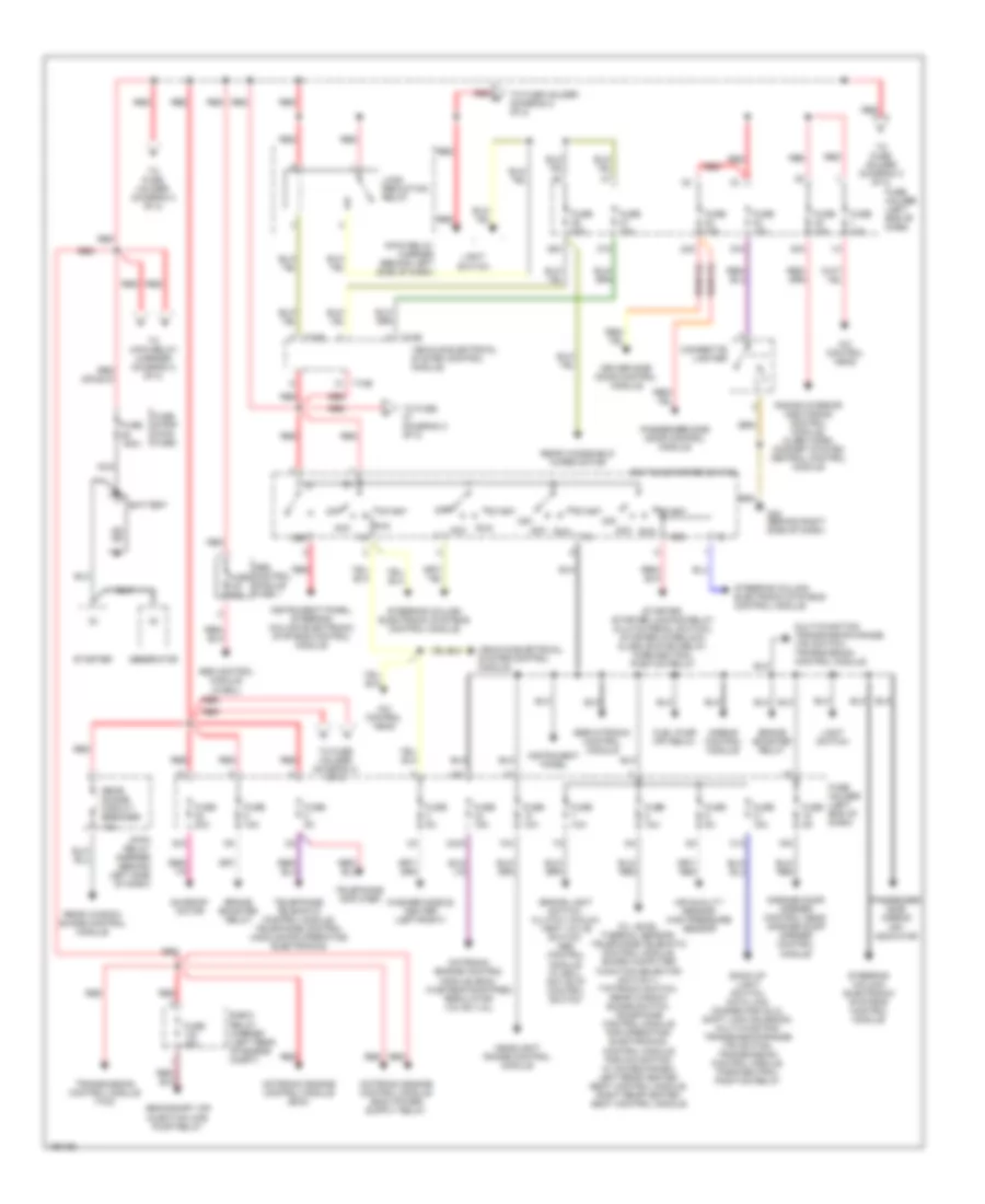
Power Distribution Wiring Diagram, without Convertible (1 of 2) for Audi A4 2004
List of elements for Power Distribution Wiring Diagram, without Convertible (1 of 2) for Audi A4 2004:
- 10a
- 16a
- 22a
- 243a
- 30a
- 31a
- 33a
- 36a
- 37a
- 38a
- 50b
- 86s
- 9-pin relay carrier (behind left side of dash)
- A/c control head
- Abs control module (w/edl)
- Abs control module fuse 1
- Acc
- Acc run
- Air quality sensor, high pressure sensor
- Airbag control module
- Back-up light switch, data link connector (dlc), shift lock solenoid, multi-function transmission range (tr) switch, transmission control module, park/neutral position relay
- Battery
- Brake booster relay
- Brake light switch, clutch vacuum vent valve switch, abs control module (w/ edl), anti-slip control switch
- Cigarette lighter
- Driver side door control module
- E-box relay carrier (left rear of engine compt)
- Fuel pump (fp) relay
- Fuse 10a
- Fuse 150a
- Fuse 15a
- Fuse 20a
- Fuse 25a
- Fuse 30a
- Fuse 40a
- Fuse 50a
- Fuse 5a
- Fuse holder (left end of dash)
- Fuse strip (main fuse)
- G33 (behind right side of dash)
- Garage door opener control head, garage door opener control module
- Generator
- Headlight range control module
- Ignition/starter switch
- Instrument panel
- Instrument panel, steering column electronic systems control module
- Light switch
- Load reduction relay
- Motronic engine control module (ecm)
- Motronic engine control module (ecm), wastegate bypass regulator valve (1.8l)
- Multi-function transmission range (tr) switch, transmission control module
- Nca
- Off
- Oil level thermal sensor, telephone/telematic control module, board computer function selector switch ii, tiptronic switch, rear window shade switch, telephone control module for operating electronics, control module for navigation w/ cd-mechanism, left rear heated seat control module, right rear heated seat control module
- Passenger side airbag off indicator
- Passenger side door control module
- Radar interior monitoring control module, alarm horn, comfort system central control module
- Rear shade circuit breaker 10a
- Rear window shade control module
- Rear windshield wiper motor
- Red
- Red b
- Run
- Secondary air injection (air) pump relay
- Servotronic control module
- Start
- Starter
- Starter, starter locking relay (clutch pedal switch), starter interlock alarm system relay, park/neutral position relay
- Steering column electronic systems control module
- Sunroof motor
- T10b
- T32b
- Telephone amplifier
- Telephone/ telematic control module, telephone control module for operating electronics
- To 4-pin relay carrier (diagram 2 of 2)
- To fuse (diagram 2 of 2)
- To fuse holder (diagram 2 of 2)
- Transmission control module (tcm)
- Vehicle electrical system control module
- Washer nozzle heater (left/right)
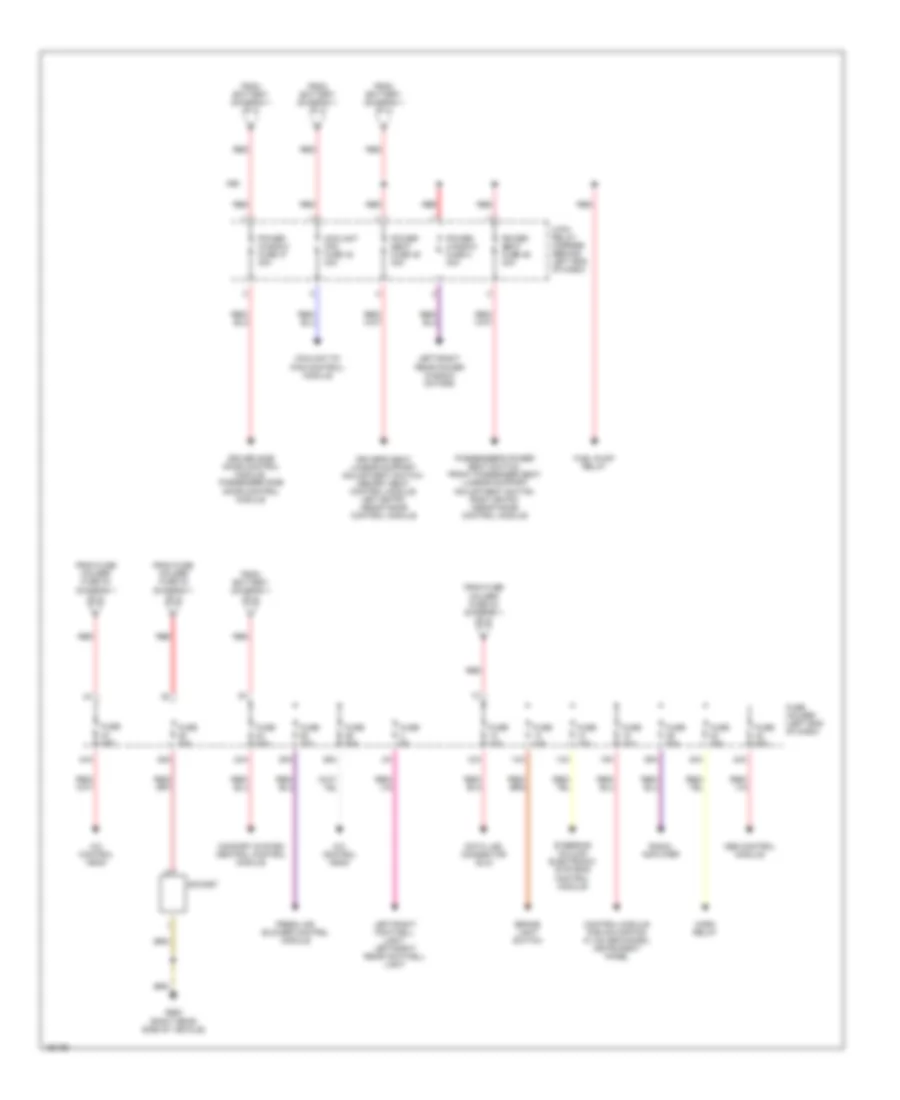
Power Distribution Wiring Diagram, without Convertible (2 of 2) for Audi A4 2004
List of elements for Power Distribution Wiring Diagram, without Convertible (2 of 2) for Audi A4 2004:
- 12a
- 13a
- 14a
- 15a
- 23a
- 24a
- 25a
- 26a
- 35a
- 39a
- 4-pin relay carrier (behind left end of dash)
- 40a
- 42a
- 44a
- A/c control head
- Abs control module
- Brake light switch
- Comfort system central control module
- Control module for navigation w/ cd mechanism, instrument panel
- Coolant fan (fc) control module 2
- Coolant fan fuse 42 40a
- Coolant fc (fan control) module
- Data link connector (dlc)
- Driver side door control module, passenger side door control module
- Driver's power seat switch, driver's seat lumbar support adjustment switch, memory seat control module
- Fresh air blower control module
- From battery (diagram 1 of 2)
- From fuse holder fuse 30 (diagram 1 of 2)
- From fuse holder fuse 33 (diagram 1 of 2)
- Fuel pump (fp) relay
- Fuse 10a
- Fuse 15a
- Fuse 20a
- Fuse 25a
- Fuse 30a
- Fuse 5a
- Fuse holder (left end of dash)
- G78 (at base of right "b" pillar)
- Horn relay
- Left rear door control module
- Left rear door control module, right rear door control module
- Left rear heated seat control module, right rear heated seat control module, a/c control head
- Left/right footwell light
- Passenger's power seat switch, front passenger seat lumbar support adjustment switch
- Power seat fuse 45 30a
- Power seat fuse 46 30a
- Power window fuse 2 30a
- Power window fuse 37 30a
- Radiator after-run fuse 14 (4.2l) 40a
- Radio, amplifier
- Red
- Right rear door control module
- Socket
- Steering column electronic systems control module