POWER DISTRIBUTION
Power Distribution Wiring Diagram (1 of 2) for Audi A6 Quattro 1996

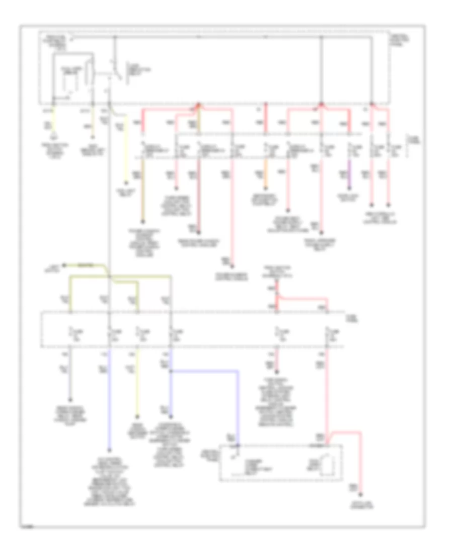
List of elements for Power Distribution Wiring Diagram (1 of 2) for Audi A6 Quattro 1996:
- (not used)
- 14a
- 15a
- 17a
- 21a
- 50b
- 86s
- 87f
- A/c control head, luggage compartment light, instrument cluster, footwell lights, front interior light, make-up mirror lights, rear fog light switch, clock, power window/sunroof control module, memory program switch, selector lever light relay, interior monitoring sensors control module relay
- A/t
- Abs control module, brake light switch
- Acc
- Air bag control module, servotronic control module, transmission control module shift lock relay, anti-theft system
- Back-up light switch, lamp control module, washer nozzle heaters, malfunction indicator lamp (mil) power seats system central locking/ alarm system/ interior light delay control module
- Battery
- Battery jump start terminal
- Brake light switch
- Central electric panel
- Central locking/ alarm system/ interior light delay control module
- Central locking/ alarm system/ interior light delay control module, radio
- Cigarette lighter
- Circuit breaker 15a
- Daytime running lights switch-on relay
- Engine control module
- Evap canister purge regulator valve, intake manifold change-over valve, egr vacuum regulator solenoid valve, oxygen sensors
- Fuel injectors
- Fuel pump
- Fuel pump relay
- Fuse 10a
- Fuse 15a
- Fuse 20a
- Fuse 5a
- Fuse panel
- G202 (behind left side of i/p)
- Generator, instrument cluster
- Headlight dimmer/ flasher switch
- Headlight washer system relay
- Ignition coils, engine control module, mass air flow sensor
- Ignition switch
- Instrument cluster
- Interior lights system
- Key-in ignition switch
- Light switch
- Luggage compartment release switch
- M/t
- Mirror adjustment switch, instrument cluster, outside air temperature display
- Off
- Red
- Run
- S1/50z
- S2/87f
- S3/15
- S3/s
- S4/5
- S4/50z
- S4/a
- S6/50a
- Shift lock solenoid, cruise control switch, rear fog light switch, fog light switch
- Start
- Starter
- Starting interlock relay
- To fuse (diagram 2 of 2)
- To load reduction relay (diagram 2 of 2)
- Transmission control module
Power Distribution Wiring Diagram (2 of 2) for Audi A6 Quattro 1996
List of elements for Power Distribution Wiring Diagram (2 of 2) for Audi A6 Quattro 1996:
- 10a
- 11a
- 12a
- 13a
- 18a
- 19a
- 75a
- 75x
- A/c control head, fresh air recirculation flap two-way valve, a/c refrigerant low pressure switch, engine coolant two- way vacuum valve fresh air blower, interior temperature sensor, a/c clutch relay
- Abs hydraulic unit, abs control module
- Central electric panel
- Circuit breaker 37 30a
- Circuit breaker 43 30a
- Circuit breaker 44 30a
- Data link connector
- Door lock switch
- Dual horn relay
- Fog light relay
- From fuel pump relay (diagram 1 of 2)
- From ignition switch (diagram 1 of 2)
- Fuse 15a
- Fuse 20a
- Fuse 25a
- Fuse 30a
- Fuse 40a
- Fuse 50a
- Fuse panel
- G202 (behind left side of i/p)
- Light switch
- Load reduction relay
- Power sunroof control module
- Power window/ sunroof control module, front power window control modules
- Rear power window control modules
- Rear window defogger switch
- Rear window wiper/washer relay, rear window washer pump
- Red
- S1/30ah
- S1/31
- S1/75
- Secondary air injection pump relay
- Third speed coolant fan control relay, coolant fan control relay
- Turn signal switch, central locking/ alarm system/ interior light delay control module, emergency flasher switch, central locking system control module (remote control)
- Washer/ wiper intermittent relay
- Windshield wiper/washer switch, windshield wiper motor, emergency flasher switch third speed coolant fan control relay, coolant fan control relay