POWER DISTRIBUTION
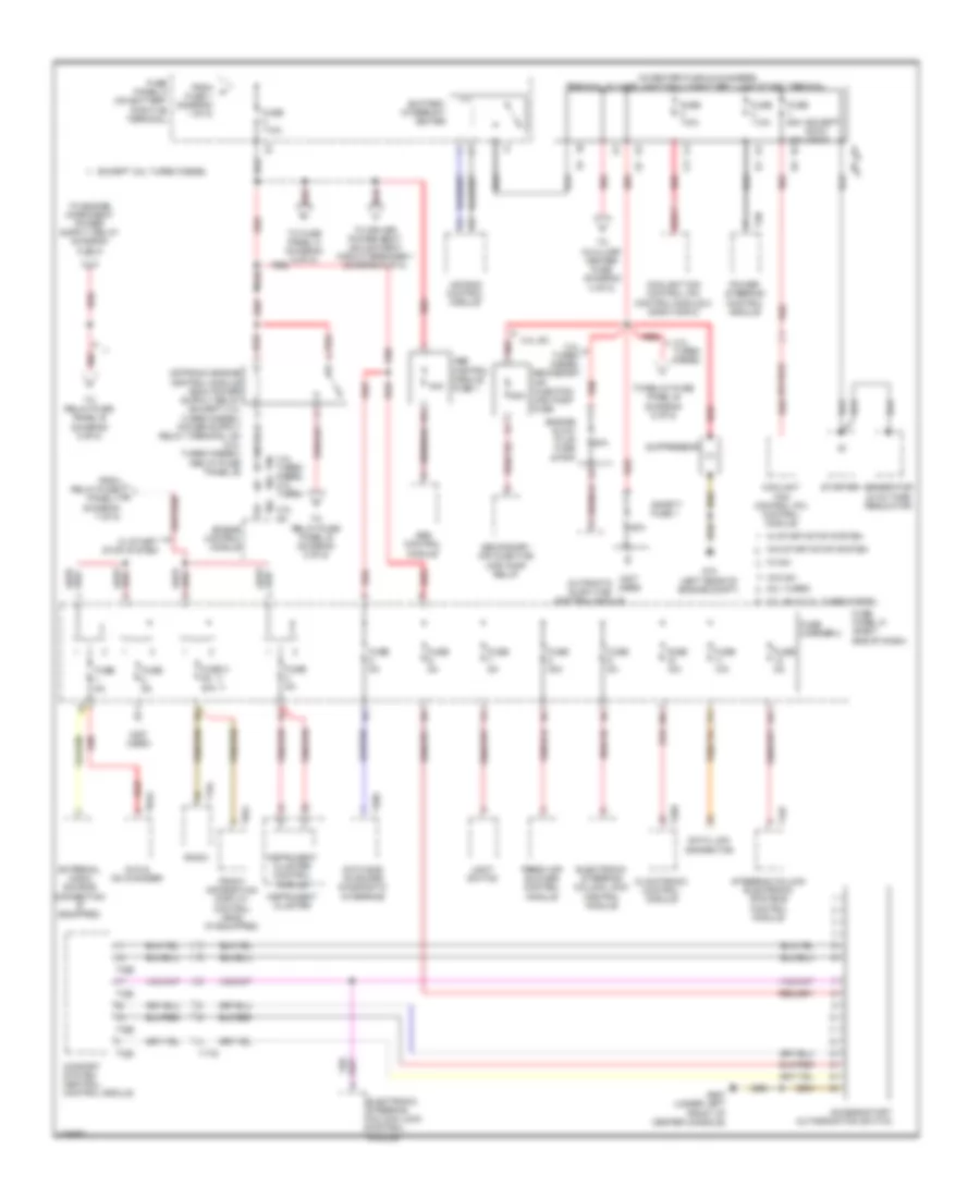
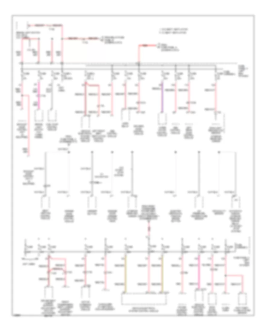
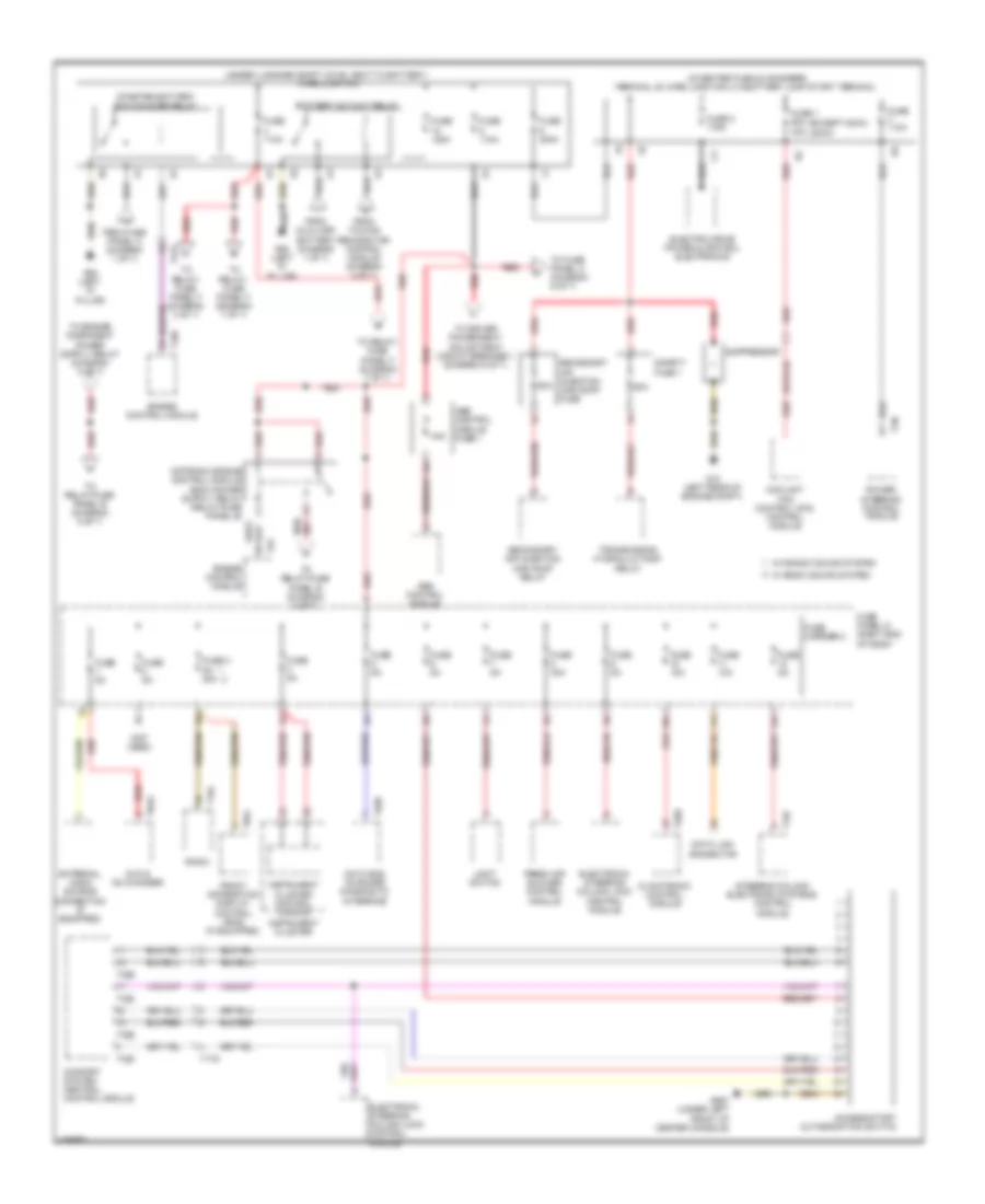
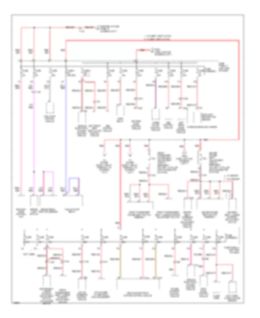
Power Distribution Wiring Diagram, Except Hybrid (1 of 8) for Audi Q5 Prestige 2014

List of elements for Power Distribution Wiring Diagram, Except Hybrid (1 of 8) for Audi Q5 Prestige 2014:
- (not used)
- 10a
- 11a
- 12a
- 2.0l turbo
- 3.0l sc & 3.0l turbo diesel
- All wheel drive control module
- Battery
- Battery monitoring control module (left side of luggage compt)
- Data bus on board diagnostic interface
- Digital sound system control module
- Electro- mechanical parking brake control module
- Electronic damping control module
- From battery monitoring control module (diagram 1 of 8)
- From fuse panel c (diagram 8 of 8)
- Front passenger's door control module
- Fuse 10a
- Fuse 110a
- Fuse 15a
- Fuse 20a
- Fuse 25a
- Fuse 30a
- Fuse 3a
- Fuse 40a
- Fuse 5a
- Fuse carrier
- Fuse carrier 1
- Fuse n/a
- Fuse panel a (on battery positive terminal)
- G51 (right "d" pillar)
- G624 (in luggage compartment near starter battery)
- Generator & voltage regulator
- Radio
- Rear lid control module
- Rear window defogger relay
- Red
- Relay/fuse panel f (right side of luggage compt)
- Right rear door control module
- Seat heating control module
- T10ag
- T12d
- T17e
- T17q
- T17r
- T20d
- T20g
- T20i
- T20m
- T27d
- T32h
- T5l
- Telephone baseplate (w/ center armrest)
- To fuse 2 (diagram 2 of 8)
- To relay/ fuse panel b (diagram 5 of 8)
- To relay/ fuse panel f (diagram 7 of 8)
- To sockets relay (diagram 4 of 8)
- To voltage stabilizer (diagram 1 of 8)
- Towing recognition control module
- Voltage stabilizer (w/ stop/ start system) (right side of luggage compt)
- W/ stop/ start system
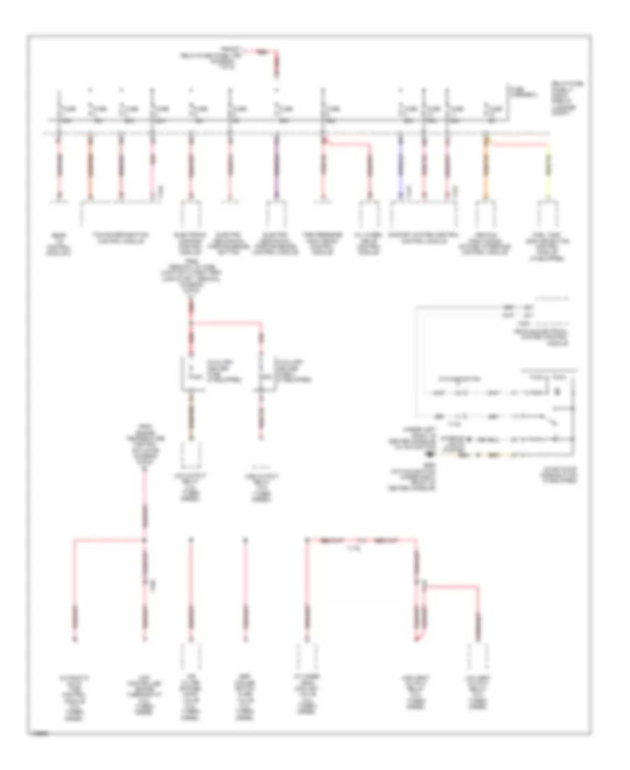
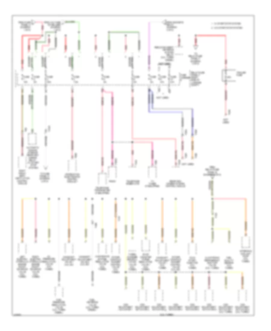
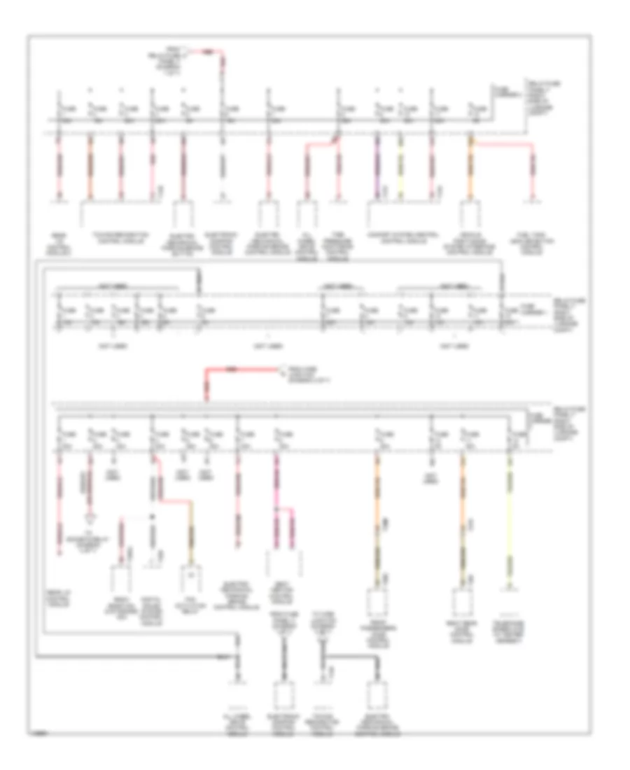
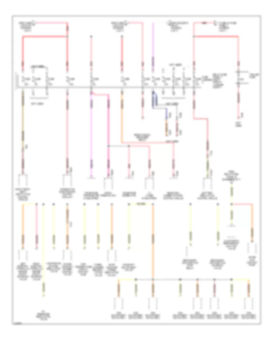
Power Distribution Wiring Diagram, Except Hybrid (2 of 8) for Audi Q5 Prestige 2014
List of elements for Power Distribution Wiring Diagram, Except Hybrid (2 of 8) for Audi Q5 Prestige 2014:
- (except 400w) (400w)
- (in center plenum chamber) terminal 30 wire junction 2 w/battery jump start terminal
- (not used)
- 10a
- 11a
- 12a
- 2.0l turbo
- 3.0l sc
- 3.0l sc & 3.0l turbo diesel
- 3.0l turbo diesel
- 3.0l turbo diesel 2.0l turbo
- 40a
- 40a b2
- 50a
- 80a
- Abs control module
- Abs control module fuse 1
- Access/start authorization switch
- Air bag control module
- Automatic glow-time control module
- Battery interrupt igniter
- Climatronic control module
- Comfort system central control module
- Coolant fan control (fc) control module
- Coolant fan control (fc) control module 2 (800w/1000w)
- Data bus on board diagnostic interface
- Data link connector
- Dvd & cd changer
- Electronic steering column lock control module
- Engine control module
- Engine glow plug fuse strip
- Except 3.0l turbo diesel
- External audio source connection (if equipped)
- Fresh air blower control module
- From a fuse 1 (diagram 1 of 8)
- From relay/fuse panel f (diagram 7 of 8)
- Front information display control head (if equipped)
- Fuse 10a
- Fuse 110a
- Fuse 3 5a 20a
- Fuse 40a
- Fuse 5a
- Fuse 60a
- Fuse carrier 2
- Fuse panel a (on battery positive terminal)
- Fuse panel d (right end of dash)
- G12 (left rear of engine compt)
- G687 (under left front of center console)
- Generator & voltage regulator
- Instrument cluster
- Instrument cluster control module
- Light switch
- Power steering control module
- Radio
- Red
- Safety fuse 1
- Secondary air injection (air) pump fuse
- Secondary air injection (air) pump relay
- Starter
- Steering column electronic systems control module
- Suppressor
- T16f
- T16l
- T17g
- T20d
- T20e
- T2n
- T32c
- T32d
- T8aa
- T8ai
- T91
- T94
- To auxiliary heater fuse (diagram 3 of 8)
- To driver power seat adjustment circuit breaker 1 (diagram 8 of 8)
- To fuse panel c (diagram 6 of 8)
- To relay/fuse panel b (diagram 5 of 8)
- W/ mmi
- W/ start/ stop system
- W/ start/stop system
- W/o mmi
- W/o start/stop system
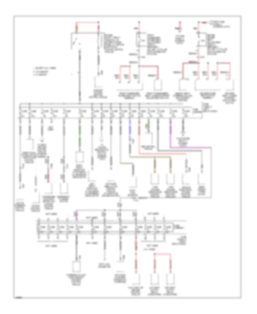
Power Distribution Wiring Diagram, Except Hybrid (3 of 8) for Audi Q5 Prestige 2014
List of elements for Power Distribution Wiring Diagram, Except Hybrid (3 of 8) for Audi Q5 Prestige 2014:
- (under left front of center console) (w/ navigation) g687
- 10a
- 11a
- 12a
- 40a
- 60a
- Air filter bypass door valve (3.0l turbo) diesel
- All wheel drive control module
- Automatic glow time control module (3.0l turbo) diesel
- Auxiliary heater fuse (if equipped)
- Auxiliary heater fuse 2 (if equipped)
- Comfort system central control module
- Cylinder head coolant valve (3.0l turbo) diesel
- Egr cooler switch over valve (3.0l turbo) diesel
- Electro- mechanical parking brake button
- Electro- mechanical parking brake control module
- Electronic damping control module
- From engine temperature control actuator (diagram 5 of 8)
- From relay/fuse panel f (diagram 7 of 8)
- From terminal 30 wire junction 2 w/battery jump start terminal (diagram 2 of 8)
- Fuel tank leak detection control module (if equipped)
- Fuse 15a
- Fuse 20a
- Fuse 30a
- Fuse 35a
- Fuse 5a
- Fuse carrier 2
- G688 (w/o navigation) (under right front of center console)
- High heat output relay (3.0l turbo) diesel
- High output relay (3.0l turbo diesel)
- Interior lights system
- Low heat output relay (3.0l turbo) diesel
- Low output relay (3.0l turbo diesel)
- Map controlled engine thermostat (3.0l turbo) diesel
- Rear lid control module 2
- Red
- Relay/fuse panel f (right side of luggage compt)
- Start/stop mode button (if equipped)
- T10d
- T12d
- T17b
- T17c
- T17o
- T17p
- T17q
- T32a
- Tire pressure monitoring control module
- Towing recognition control module
- Vehicle electrical system control module
- Vehicle positioning system interface control module
- W/o navigation
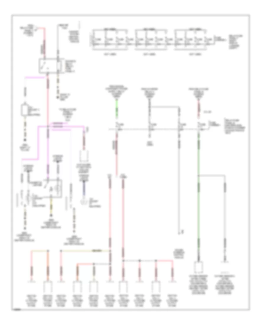
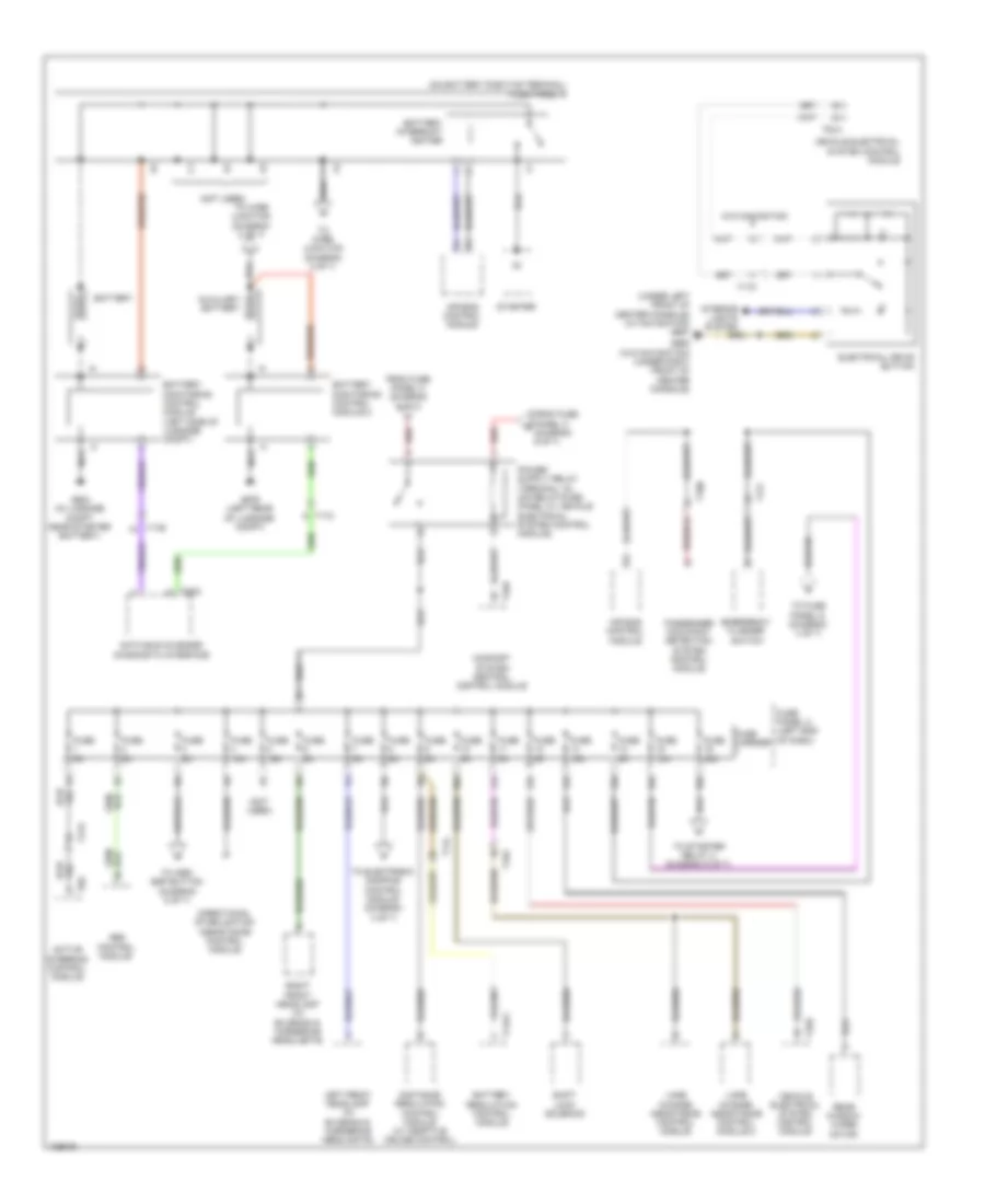
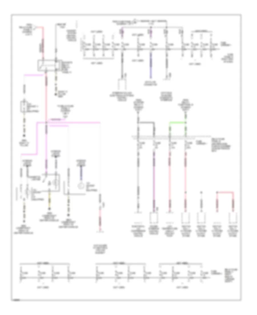
Power Distribution Wiring Diagram, Except Hybrid (4 of 8) for Audi Q5 Prestige 2014
List of elements for Power Distribution Wiring Diagram, Except Hybrid (4 of 8) for Audi Q5 Prestige 2014:
- (not used)
- (right "c" pillar) g663
- 12v socket (if equipped)
- 12v socket 3 (if equipped)
- 13a
- 14a
- 15a
- 17a
- 2.0l turbo
- 3.0l sc
- Cigarette lighter
- Comfort system central control module
- Cup holder w/ heating & cooling element
- From relay/fuse panel b (diagram 5 of 8)
- From relay/fuse w panel f (diagram 1 of 8)
- From starter relay 2 (diagram 5 of 8)
- Fuse 15a
- Fuse 20a
- Fuse 5a
- Fuse carrier 1
- Fuse carrier 4
- Fuse n/a
- G663 (right "c" pillar)
- G688 (under right front of center console)
- Ignition coil 1 w/ power output stage
- Ignition coil 2 w/ power output stage
- Ignition coil 3 w/ power output stage
- Ignition coil 4 w/ power output stage
- Ignition coil 5 w/ power output stage
- Ignition coil 6 w/ power output stage
- Interior lights system
- Nca
- Oxygen sensor 2 after catalytic converter & oxygen sensor heater 2 after catalytic converter
- Oxygen sensor after three way catalytic converter & oxygen sensor heater 1 after catalytic converter
- Power steering control module
- Relay/fuse panel b (driver's side plenum chamber on electronics box)
- Relay/fuse panel f (right side of luggage compt)
- Sockets relay (relay/ fuse panel f)
- T32c
- T4av
- T6h
- To relay/fuse panel f (diagram 7 of 8)
Power Distribution Wiring Diagram, Except Hybrid (5 of 8) for Audi Q5 Prestige 2014
List of elements for Power Distribution Wiring Diagram, Except Hybrid (5 of 8) for Audi Q5 Prestige 2014:
- 10a
- 11a
- 12a
- 16a
- 2.0l turbo
- 3.0l sc
- 3.0l turbo diesel
- Auxiliary engine coolant pump relay (3.0l sc)
- Charge air cooling pump (3.0l sc)
- Coolant fan control (fc) control module
- Coolant fan control (fc) control module 2 (800w/1000w)
- Crankcase ventilation shut-off valve (3.0l sc)
- Engine control module
- Engine control module (ecm)
- Engine temperature control actuator (3.0l sc)
- Evap canister purge regulator valve 1 (3.0l sc)
- Except 3.0l turbo diesel
- From fuse h panel c (diagram 8 of 8)
- From terminal 30 wire junction 2 w/ battery jump start terminal (diagram 2 of 8)
- From voltage stabilizer (diagram 1 of 8)
- Fuel metering valve
- Fuel pressure regulator valve
- Fuse 10 10a 15a
- Fuse 15a
- Fuse 5 5a 10a
- Fuse 5a
- Fuse 7 10a 15a
- Fuse carrier 1
- Heated oxygen sensor & oxygen sensor heater
- Left electrohydraulic engine mount solenoid valve
- Mass air flow sensor
- Nca
- Nox sensor & nox sensor control module
- Nox sensor 2 & nox sensor control module 2 (w/ reducing agent metering system)
- Oil level thermal sensor
- Oil pressure regulation valve
- Oxygen sensor heater 1 after three way catalytic converter & oxygen sensor after three way catalytic converter (2.0l turbo) heated oxygen sensor 2 & oxygen sensor heater 2 (3.0l sc)
- Red
- Reducing agent metering system control module (if equipped)
- Relay/fuse panel b (driver's side plenum chamber on electronics box)
- Right electrohydraulic engine mount solenoid valve
- Secondary air injection (air) pump relay (3.0l sc)
- Secondary air injection (air) solenoid valve (3.0l sc)
- Starter
- Starter relay
- Starter relay 2
- T14e
- T17q
- T17r
- T5l
- T91
- T94
- To climatronic refrigerant shut-off valve (diagram 7 of 8)
- To fuse panel c (diagram 6 of 8)
- To map controlled engine thermostat (diagram 3 of 8)
- To relay/fuse panel b (diagram 4 of 8)
- Transmission control module (tcm)
- W/ start/stop system
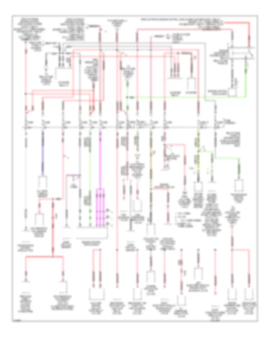
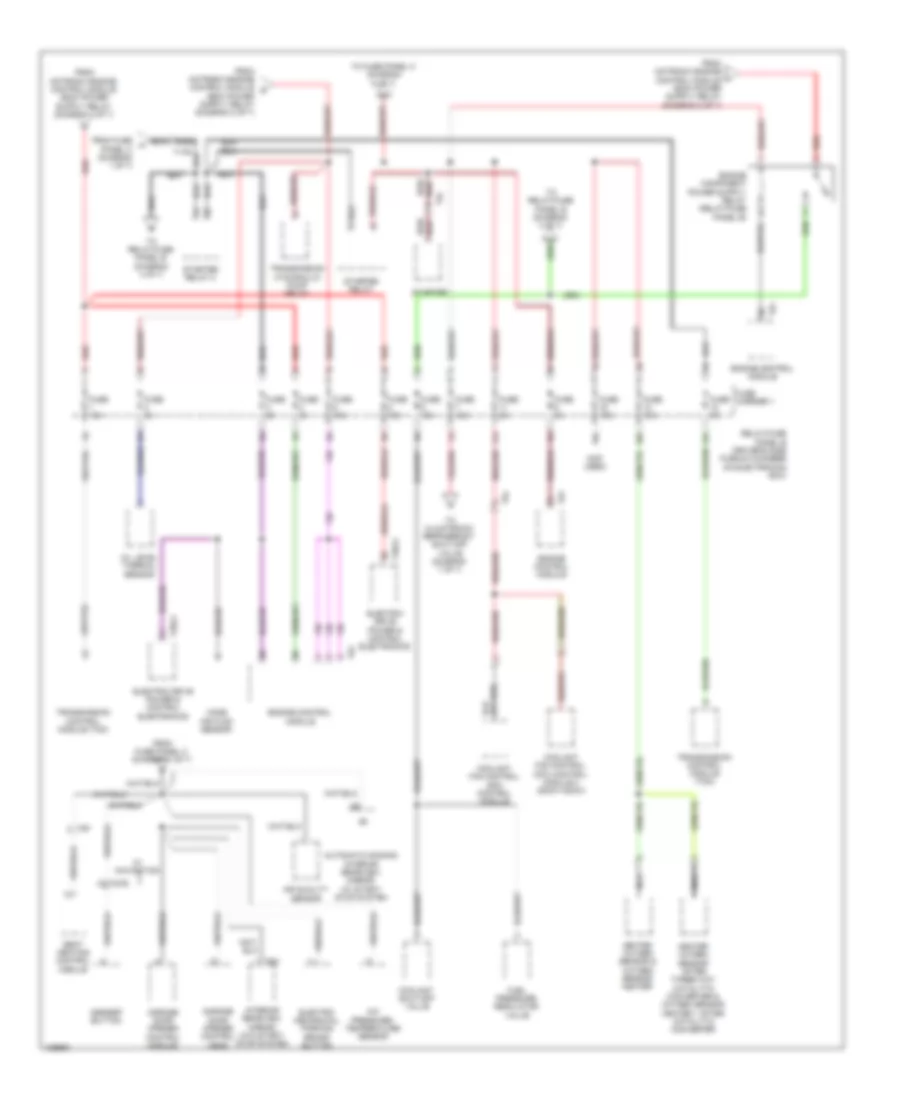
Power Distribution Wiring Diagram, Except Hybrid (6 of 8) for Audi Q5 Prestige 2014
List of elements for Power Distribution Wiring Diagram, Except Hybrid (6 of 8) for Audi Q5 Prestige 2014:
- (not used)
- 10a
- 11a
- 12a
- 3.0l sc
- A/c pressure/ temperature sensor
- Abs control module
- Active steering control module
- Air quality sensor
- Alarm horn
- Anti-theft alarm system sensor
- Asr/esp button
- Automatic dimming interior rearview mirror relay (w/ start/ stop system)
- Brake light switch (3.0l sc & 2.0l turbo)
- Brake light switch (3.0l turbo diesel)
- Cupholder w/ heating & cooling element
- Driver seat lumbar support adjustment switch (w/o power seats)
- Driver's door control module
- Electro- mechanical parking brake button
- Exhaust door control unit (if equipped)
- Exhaust door control unit 2 (if equipped)
- From front passenger power seat adjustment circuit breaker 1 (diagram 8 of 8)
- From fuse panel a (diagram 2 of 8)
- From fuse panel c (diagram 8 of 8)
- From relay/fuse panel b (diagram 5 of 8)
- Front passenger's seat lumbar support adjustment switch
- Fuel pump control module
- Fuse 10a
- Fuse 15a
- Fuse 20a
- Fuse 25a
- Fuse 30a
- Fuse 35a
- Fuse 4 5a (or 25a)
- Fuse 5 15a 30a
- Fuse 5a
- Fuse carrier 2
- Fuse carrier 3
- Fuse n/a
- Fuse panel c (left end of dash)
- Garage door opener control head
- Garage door opener control module
- Horn relay
- Interior rearview mirror
- Left front seat ventilation control module
- Left rear door control module
- Power sunroof control module
- Rain/light recognition sensor
- Red
- Roof blind control module
- Seat heating control module
- T10m
- T10p
- T17b
- T17e
- T17l
- T17m
- T17n
- T17q
- T20f
- T20h
- T27a
- T27b
- T3c
- T4av
- T5d
- T6e
- T6f
- T6l
- T8c
- T8f
- Vehicle electrical system control module
- W/ navigation
- W/ seat ventilation
- W/o seat ventilation
- W/o start/ stop system
- Wiper motor control module
Power Distribution Wiring Diagram, Except Hybrid (7 of 8) for Audi Q5 Prestige 2014
List of elements for Power Distribution Wiring Diagram, Except Hybrid (7 of 8) for Audi Q5 Prestige 2014:
- (2.0l turbo)
- (not used)
- 10a
- 30a
- After-run coolant pump (2.0l turbo)
- Automatic dimming interior rearview mirror relay (w/ start/ stop system)
- Cam adjustment actuator 1
- Cam adjustment actuator 2
- Cam adjustment actuator 3
- Cam adjustment actuator 4
- Cam adjustment actuator 5
- Cam adjustment actuator 6
- Cam adjustment actuator 7 (2.0l turbo)
- Cam adjustment actuator 8 (2.0l turbo)
- Camshaft adjustment valve 1 (2.0l turbo)
- Camshaft adjustment valve 1 (3.0l sc)
- Camshaft adjustment valve 2 (3.0l sc)
- Climatronic refrigerant shut-off valve (2.0l turbo)
- Cold start injector (2.0l turbo)
- Evap canister purge regulator valve 1 (2.0l turbo)
- From fuse x panel a (diagram 1 of 8)
- From relay/fuse panel b (diagram 5 of 8)
- From sockets relay (diagram 4 of 8)
- From voltage f stabilizer (diagram 1 of 8)
- Fuel metering valve (3.0l turbo diesel)
- Fuel pressure regulation valve (3.0l turbo diesel)
- Fuel quality sensor (2.0l turbo)
- Fuse 15a
- Fuse 30a
- Fuse 5a
- Fuse 7.5a
- Fuse carrier
- Fuse n/a
- Information electronics control module 1
- Intake manifold runner control valve (2.0l turbo)
- Intake manifold runner control valve (3.0l sc)
- Left electro- hydraulic engine mount solenoid valve (2.0l turbo)
- Oil pressure regulation valve (2.0l turbo)
- Radio
- Rearview camera system control module
- Red
- Reducing agent metering system relay (3.0l turbo diesel)
- Relay/fuse panel f (right side of luggage compt)
- Right electro- hydraulic engine mount solenoid valve (2.0l turbo)
- Right front seat ventilation control module
- T10ag
- T10d
- T14f
- T17q
- T17w
- T20c
- T2da
- T2db
- T2dy
- T2dz
- T4aj
- T4aq
- T54b
- T6k
- T8ao
- Telephone baseplate
- Telephone transceiver (if equipped)
- To fuse panel d (diagram 2 of 8)
- To relay/fuse panel f (diagram 3 of 8)
- Trailer fuse
- Turbo- charger recircu- lation valve (2.0l turbo)
- Tv tuner (if equipped)
- W/ start/stop system
- W/o start/stop system
- Wastegate bypass regulator valve (2.0l turbo)
Power Distribution Wiring Diagram, Except Hybrid (8 of 8) for Audi Q5 Prestige 2014
List of elements for Power Distribution Wiring Diagram, Except Hybrid (8 of 8) for Audi Q5 Prestige 2014:
- (not used)
- 10a
- 11a
- 12a
- 13a
- 14a
- 15a
- 16a
- 2.0l turbo
- Abs control module
- Active steering control module
- Air bag control module
- Auxiliary air heater control module
- Comfort system central control module
- Data bus on board diagnostic interface
- Data link connector
- Directional stabilization assistance control module
- Distance regulation control module (w/ adaptive cruise control)
- Driver power seat adjustment circuit breaker 1 (on left "a" pillar 6-pin connector station)
- Driver power seat switch assembly
- Driver's seat lumbar support adjustment switch
- Emergency flasher switch
- Except 2.0l turbo
- From fuse panel a (diagram 2 of 8)
- Front passenger power seat adjustment circuit breaker 1 (on left "a" pillar 6-pin connector station)
- Front passenger power seat switch assembly
- Front passenger's seat lumbar support adjustment switch
- Fuse 10a
- Fuse 15a
- Fuse 40a
- Fuse 5a
- Fuse carrier
- Fuse carrier 1
- Fuse n/a
- Fuse panel c (left end of dash)
- Fuse panel d (right end of dash)
- High heat output relay (if equipped)
- Lane change assistance control module
- Lane change assistance control module 2
- Left front headlamp (w/ bi-xenon & cornering headlights)
- Low heat output relay (if equipped)
- Memory seat/ steering column adjustment control
- Passenger occupant detection system control module
- Rear window wiper motor
- Red
- Right front headlamp (w/ bi-xenon & cornering headlights)
- Shift lock solenoid
- Steering column electronics systems control module
- T10m
- T10n
- T10p
- T12l
- T16f
- T16v
- T17c
- T17e
- T17f
- T20d
- T32b
- T32d
- T8g
- To fuse panel c (diagram 6 of 8)
- To seat heating control module (diagram 6 of 8)
- To starter relay 2 (diagram 5 of 8)
- To towing recognition control module (diagram 1 of 8)
- Vehicle electrical system control module
- W/ memory
- W/o memory
Power Distribution Wiring Diagram, Hybrid (1 of 7) for Audi Q5 Prestige 2014
List of elements for Power Distribution Wiring Diagram, Hybrid (1 of 7) for Audi Q5 Prestige 2014:
- (not used)
- (on battery positive terminal) fuse panel a
- (under left front of center console) (w/ navigation) g687
- 10a
- 11a
- 12a
- 13a
- 14a
- 15a
- 16a
- Abs control module
- Active steering control module
- Air bag control module
- Auxiliary battery
- Battery
- Battery interrupt igniter
- Battery monitoring control module (left side of luggage compt)
- Battery monitoring control module 2
- Battery regulation control module
- Comfort system central control module
- Data bus on board diagnostic interface
- Directional stabilization assistance control module
- Distance regulation control module (w/ adaptive cruise control)
- Electrical drive button
- Emergency flasher switch
- From fuse panel c (diagram 6 of 7)
- Fuse 10a
- Fuse 15a
- Fuse 40a
- Fuse 5a
- Fuse carrier
- Fuse panel c (left end of dash)
- G624 (in luggage compt near starter battery)
- G676 (left rear of luggage compt)
- G688 (w/o navigation) (under right front of center console)
- Interior lights system
- Lane change assistance control module
- Lane change assistance control module 2
- Left front headlamp (w/ bi-xenon & cornering headlights)
- Nca
- Passenger occupant detection system control module
- Rear window wiper motor
- Red
- Right front headlamp (w/ bi-xenon & cornering headlights)
- Shift lock solenoid
- Starter
- T10n
- T14ax
- T14l
- T16v
- T17c
- T17e
- T17f
- T20d
- T32a
- T32b
- T32d
- T8g
- To asr/ esp button (diagram 5 of 7)
- To electronic damping control module (diagram 3 of 7)
- To fuse panel d (diagram 4 of 7)
- To starter relay 2 (diagram 5 of 7)
- To wire junction (diagram 2 of 7)
- Vehicle electrical system control module
- W/o navigation
Power Distribution Wiring Diagram, Hybrid (2 of 7) for Audi Q5 Prestige 2014
List of elements for Power Distribution Wiring Diagram, Hybrid (2 of 7) for Audi Q5 Prestige 2014:
- (400w)
- (except 400w)
- (in center plenum chamber) terminal 30 wire junction 2 w/battery jump start terminal
- (not used)
- (under luggage compt cove, next to battery) wire junction
- 10a
- 11a
- 12a
- 40a
- 50a
- Abs control module
- Abs control module fuse 1
- Access/start authorization switch
- Battery cut-out relay
- Climatronic control module
- Comfort system central control module
- Coolant fan control (cfc) control module
- Data bus on board diagnostic interface
- Data link connector
- Dvd & cd changer
- Electric drive power & control electronics
- Electronic steering column lock control module
- Engine control module
- External audio source connection (if equipped)
- Fresh air blower control module
- From auxiliary battery (diagram 1 of 7)
- From fuse panel a (diagram 1 of 7)
- From towing recognition control module (diagram 3 of 7)
- Front information display control head (if equipped)
- Fuse 1 60a 40a
- Fuse 10a
- Fuse 110a
- Fuse 125a
- Fuse 2 175a
- Fuse 200a
- Fuse 3 5a 20a
- Fuse 40a
- Fuse 5a
- Fuse carrier 2
- Fuse panel d (right end of dash)
- G12 (left rear of engine compt)
- G50 (left "d" pillar)
- G687 (under left front of center console)
- Instrument cluster
- Instrument cluster control module
- Light switch
- Power steering control module
- Radio
- Red
- Safety fuse 1
- Secondary air injection (air) pump fuse
- Secondary air injection (air) pump relay
- Starter battery switch-over relay
- Steering column electronic systems control module
- Suppressor
- T105
- T16f
- T16l
- T17g
- T17r
- T20d
- T20e
- T2n
- T32c
- T32d
- T8aa
- T8ai
- T91
- To driver power seat adjustment circuit breaker 1 (diagram 6 of 7)
- To fuse panel c (diagram 6 of 7)
- To relay/ fuse panel f (diagram 3 of 7)
- To relay/ fuse panel f (diagram 7 of 7)
- To relay/fuse panel b (diagram 5 of 7)
- Transmission hydraulic pump relay
- W/ basic sound system
- W/o basic sound system
Power Distribution Wiring Diagram, Hybrid (3 of 7) for Audi Q5 Prestige 2014
List of elements for Power Distribution Wiring Diagram, Hybrid (3 of 7) for Audi Q5 Prestige 2014:
- (not used)
- 10a
- 11a
- 12a
- All wheel drive control module
- Comfort system central control module
- Digital sound system control module
- Electro- mechanical parking brake button
- Electro- mechanical parking brake control module
- Electronic damping control module
- Fan activation relay
- From fuse panel c (diagram 1 of 7)
- From relay/fuse panel f (diagram 7 of 7)
- From wire junction (diagram 2 of 7)
- Front passenger's door control module
- Fuel tank leak detection control module
- Fuse 10a
- Fuse 15a
- Fuse 20a
- Fuse 25a
- Fuse 30a
- Fuse 35a
- Fuse 3a
- Fuse 40a
- Fuse 5a
- Fuse carrier
- Fuse carrier 1
- Fuse carrier 2
- Fuse n/a
- Radio (basic mmi & standard mmi)
- Rear lid control module
- Rear lid control module 2
- Red
- Relay/fuse panel f (right side of luggage compt)
- Right rear door control module
- Seat heating control module
- T10ag
- T12d
- T17o
- T17p
- T20g
- T20i
- T20m
- T27d
- T32h
- Telephone baseplate (w/ center armrest)
- Tire pressure monitoring control module
- To sockets relay (diagram 4 of 7)
- To wire junction (diagram 2 of 7)
- Towing recognition control module
- Vehicle positioning system interface control module
Power Distribution Wiring Diagram, Hybrid (4 of 7) for Audi Q5 Prestige 2014
List of elements for Power Distribution Wiring Diagram, Hybrid (4 of 7) for Audi Q5 Prestige 2014:
- (not used)
- (right "c" pillar) g663
- 10a
- 11a
- 12a
- 12v socket (if equipped)
- 12v socket 3 (if equipped)
- 13a
- 14a
- 15a
- 17a
- Cigarette lighter
- Comfort system central control module
- Cup holder w/ heating & cooling element
- Data bus on board diagnostic interface
- Data link connector
- Electrical a/c compressor control module
- From fuse panel c g (diagram 1 of 7)
- From relay/ fuse panel b (diagram 5 of 7)
- From relay/fuse v panel f (diagram 3 of 7)
- From starter relay 2 (diagram 5 of 7)
- Fuse 10a
- Fuse 20a
- Fuse 5a
- Fuse carrier 1
- Fuse carrier 4
- Fuse n/a
- Fuse panel d (right end of dash)
- G663 (right "c" pillar)
- G688 (under right front of center console)
- Ignition coil 1 w/ power output stage
- Ignition coil 2 w/ power output stage
- Ignition coil 3 w/ power output stage
- Ignition coil 4 w/ power output stage
- Interior lights system
- Low temperature circuit coolant pump
- Nca
- Power steering control module
- Relay/fuse panel b (driver's side plenum chamber on electronics box)
- Relay/fuse panel f (right side of luggage compt)
- Sockets relay (relay/ fuse panel f)
- Steering column electronic systems control module
- T16f
- T17c
- T20d
- T32c
- T4av
- T6h
- To relay/fuse panel f (diagram 7 of 7)
Power Distribution Wiring Diagram, Hybrid (5 of 7) for Audi Q5 Prestige 2014
List of elements for Power Distribution Wiring Diagram, Hybrid (5 of 7) for Audi Q5 Prestige 2014:
- (not used)
- 10a
- 11a
- 12a
- 16a
- A/c pressure/ temperature sensor
- Air quality sensor
- Asr/esp button
- Automatic dimming interior rearview mirror (w/ start/ stop system
- Coolant fan control (cfc) control module
- Coolant fan control (cfc) control module 2 (800w/1000w)
- Coolant shut-off valve
- Electric drive power & control electronics
- Electro- mechanical parking brake button
- Engine control module
- From fuse h panel c (diagram 1 of 7)
- From fuse panel c (diagram 1 of 7)
- From motronic engine control module o
- Fuel pressure regulator valve
- Fuse 10a
- Fuse 15a
- Fuse 5a
- Fuse carrier 1
- Garage door opener control head
- Garage door opener control module
- Heated oxygen sensor & oxygen sensor heater
- Heater oxygen sensor after three way catalytic converter & oxygen sensor heater 1 after catalytic converter
- Interior rearview mirror (w/o start/ stop system
- Mass air flow sensor
- Nca
- Oil level thermal sensor
- Red
- Relay/fuse panel b (driver's side plenum chamber on electronics box)
- Seat heating control module
- Starter
- Starter relay
- Starter relay 2
- T17e
- T17r
- T28jx
- T5l
- T8c
- T8f
- T91
- To climatronic refrigerant shut-off valve (diagram 7 of 7)
- To fuse panel c (diagram 6 of 7)
- To relay/fuse panel b (diagram 4 of 7)
- Transmission control module (tcm)
- Transmission hyduraulic pump relay
- W/ navigation
Power Distribution Wiring Diagram, Hybrid (6 of 7) for Audi Q5 Prestige 2014
List of elements for Power Distribution Wiring Diagram, Hybrid (6 of 7) for Audi Q5 Prestige 2014:
- (not used)
- 10a
- 11a
- 12a
- 15a
- Abs control module
- Active steering control module
- Alarm horn
- Anti-theft alarm system sensor
- Brake light switch
- Brake pedal position sensor
- Cup holder w/ heating & cooling element
- Driver power seat adjustment circuit breaker 1 (on left "a" pillar 6-pin connector station)
- Driver power seat switch assembly
- Driver seat lumbar support adjustment switch (w/o power seats)
- Driver's door control module
- Driver's seat lumbar support adjustment switch
- Exhaust door control unit
- From relay/fuse panel b (diagram 5 of 7)
- From wire junction (diagram 2 of 7)
- Front passenger power seat adjustment circuit breaker 1 (on left "a" pillar 6-pin connector station)
- Front passenger power seat switch assembly
- Front passenger's seat lumbar support adjustment switch
- Fuel pump control module
- Fuse 10a
- Fuse 15a
- Fuse 20a
- Fuse 25a
- Fuse 30a
- Fuse 35a
- Fuse 4 5a (or 25a)
- Fuse 5 15a 30a
- Fuse 5a
- Fuse carrier 2
- Fuse carrier 3
- Fuse n/a
- Fuse panel c (left end of dash)
- Horn relay
- Interior rearview mirror
- Left front seat ventilation control module
- Left rear door control module
- Memory seat/ steering column adjustment control module
- Power sunroof control module
- Rain/light recognition sensor
- Red
- Roof blind control module
- T10m
- T10p
- T12l
- T17b
- T17e
- T17l
- T17m
- T17n
- T17q
- T20f
- T20h
- T27a
- T27b
- T3c
- T4av
- T5d
- T6e
- T6f
- T6l
- Vacuum pump relay
- Vehicle electrical system control module
- W/ memory
- W/ seat ventilation
- W/o memory
- W/o seat ventilation
- Wiper motor control module
Power Distribution Wiring Diagram, Hybrid (7 of 7) for Audi Q5 Prestige 2014
List of elements for Power Distribution Wiring Diagram, Hybrid (7 of 7) for Audi Q5 Prestige 2014:
- (not used)
- 10a
- 11a
- 12a
- 30a
- After run coolant pump
- Battery regulation control module
- Cam adjustment actuator 1
- Cam adjustment actuator 2
- Cam adjustment actuator 3
- Cam adjustment actuator 4
- Cam adjustment actuator 5
- Cam adjustment actuator 6
- Cam adjustment actuator 7
- Cam adjustment actuator 8
- Camshaft adjustment valve 1
- Climatronic refrigerant shut-off valve
- Evap canister purge regulator valve 1
- From relay/fuse panel b (diagram 5 of 7)
- From sockets relay (diagram 4 of 7)
- From wire b junction (diagram 2 of 7)
- From wire w junction (diagram 2 of 7)
- Fuse 15a
- Fuse 30a
- Fuse 5a
- Fuse 7.5a
- Fuse carrier
- Fuse n/a
- High temperature circuit coolant pump
- Information electronics control module 1
- Intake manifold runner control valve
- Left electro- hydraulic engine mount solenoid valve
- Oil pressure regulation valve
- Radio (premium mmi)
- Rear window defogger relay
- Rearview camera system control module
- Red
- Relay/fuse panel f (right side of luggage compt)
- Right electro- hydraulic engine mount solenoid valve
- Right front seat ventilation control module
- Secondary air injection pump relay
- Secondary air injection solenoid valve
- T10ag
- T14ax
- T14f
- T14l
- T20c
- T2da
- T2db
- T2dy
- T2dz
- T4aj
- T4aq
- T54b
- T6k
- T8ao
- Telephone baseplate
- Telephone transceiver (if equipped)
- To relay/fuse panel f (diagram 3 of 7)
- Trailer fuse
- Turbo- charger recircu- lation valve
- Tv tuner (if equipped)
- Wastegate bypass regulator valve