
SHIFT INTERLOCK
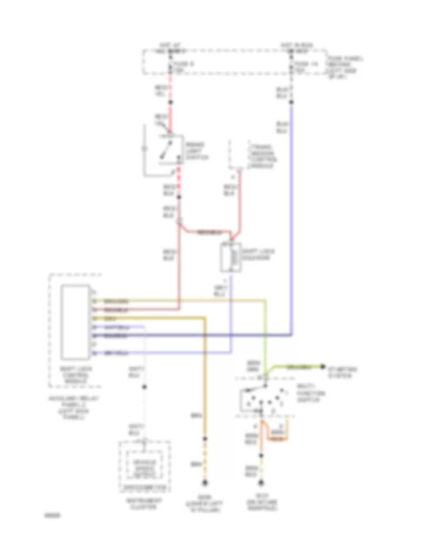
Shift Interlock Wiring Diagram for Audi 100 CS 1994
List of elements for Shift Interlock Wiring Diagram for Audi 100 CS 1994:
AIR CONDITIONINGANTI-THEFTCOMPUTER DATA LINESANTI-LOCK BRAKESDEFOGGERSCRUISE CONTROLELECTRONIC POWER STEERINGHORNEXTERIOR LIGHTSCOOLING FANINTERIOR LIGHTSGROUND DISTRIBUTIONHEADLIGHTSENGINE PERFORMANCEINSTRUMENT CLUSTERPOWER DOOR LOCKSPOWER DISTRIBUTIONMEMORY SYSTEMSPOWER SEATSPOWER TOP/SUNROOFPOWER MIRRORSPOWER WINDOWSRADIOSHIFT INTERLOCKSTARTING/CHARGINGSUPPLEMENTAL RESTRAINTSTRANSMISSIONTRUNK, TAILGATE, FUEL DOORWARNING SYSTEMSWIPER/WASHER