SHIFT INTERLOCK
Park Brake Release Wiring Diagram for Audi A5 2.0T 2011

List of elements for Park Brake Release Wiring Diagram for Audi A5 2.0T 2011:
- 12a
- Abs control module (left rear of engine compt)
- Auto hold button
- Computer data lines system
- Convertible
- Discontinued phased in modification
- Electro- mechanical parking brake control module (right rear of luggage compt)
- Electro-mechanical parking brake button
- Fuse 30a
- Fuse 5a
- Fuse carrier 2
- Fuse carrier 3
- Fuse carrier 4
- G51 (right side of luggage compt)
- Hot at all times
- Interior lights system
- Left parking brake motor
- Relay/ fuse carrier luggage compartment sf (right side of luggage compt)
- Right parking brake motor
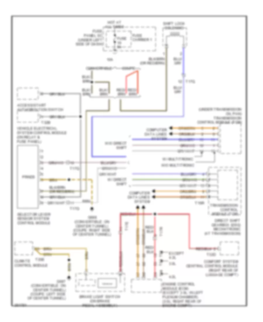
Shift Interlock Wiring Diagram for Audi A5 2.0T 2011
List of elements for Shift Interlock Wiring Diagram for Audi A5 2.0T 2011:
- (under transmission oil pan) transmission control module (tcm)
- 10a
- 3.0l
- 4.2l
- Access/start authorization switch
- Brake light switch (on brake pedal assembly)
- Climate control module
- Comfort system central control module (right rear of luggage compt)
- Computer data lines system
- Convertible
- Coupe
- Direct shift gearbox (dsg) mechatronic (at transmission)
- Engine control module (ecm) (except 3.0l: in left plenum chamber) (3.0l: right rear of engine compt)
- Except 4.2l
- Fuse 5a
- Fuse carrier 1
- Fuse panel sc (under left side of dash)
- G687 (convertible: on center tunnel) (coupe: left side of center tunnel)
- G688 (convertible: on center tunnel) (coupe: right side of center tunnel)
- Hot at all times
- Prnds
- Selector lever sensor system control module
- Shift lock solenoid
- T16r
- T17e
- T17q
- T17r
- T20e
- T32b
- T32d
- T94
- Transmission control module (tcm)
- Vehicle electrical system control module (on relay & fuse panel)
- W/ direct shift
- W/ multitronic
- W/o direct shift
- W/o multitronic
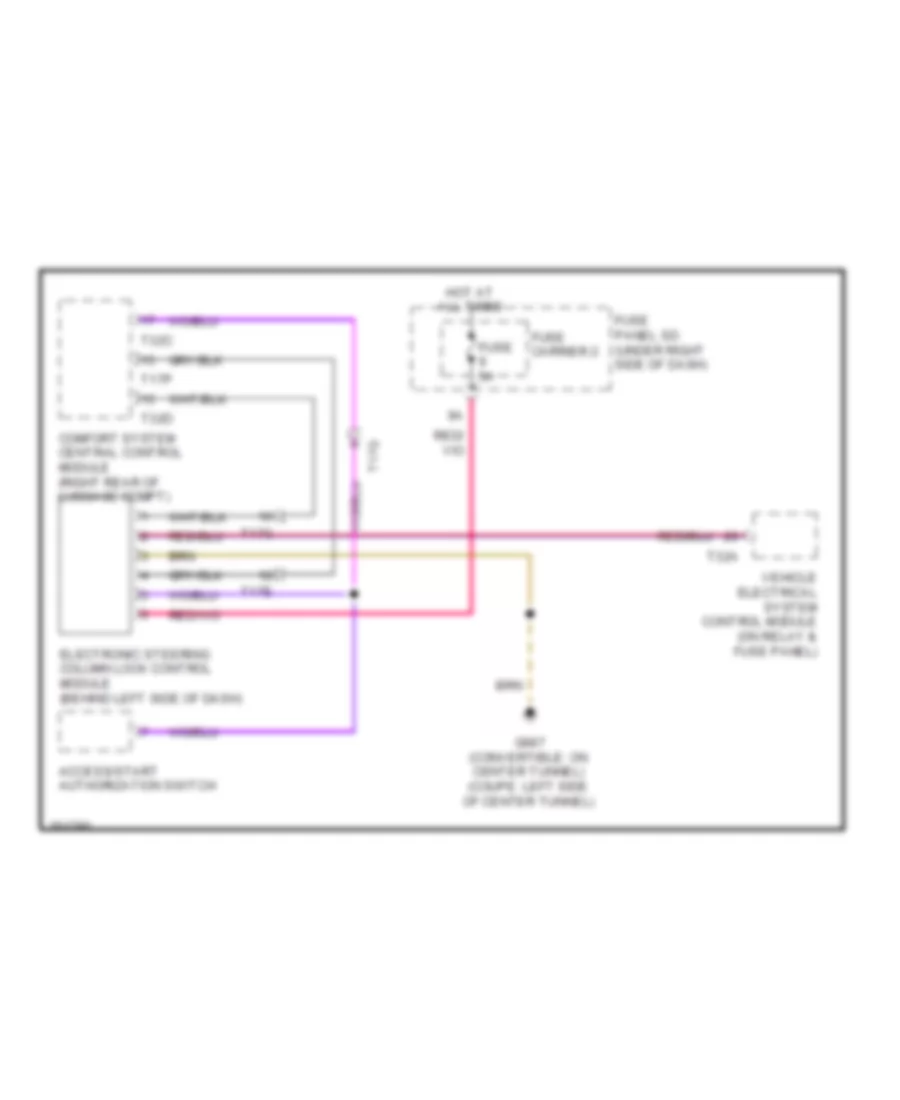
Steering Column Wiring Diagram for Audi A5 2.0T 2011
List of elements for Steering Column Wiring Diagram for Audi A5 2.0T 2011:
- Access/start authorization switch
- Comfort system central control module (right rear of luggage compt)
- Electronic steering column lock control module (behind left side of dash)
- Fuse 5a
- Fuse carrier 2
- Fuse panel sd (under right side of dash)
- G687 (convertible: on center tunnel) (coupe: left side of center tunnel)
- Hot at all times
- T17e
- T17g
- T17p
- T32a
- T32c
- T32d
- Vehicle electrical system control module (on relay & fuse panel)