SHIFT INTERLOCK
Electronic Parking Brake Wiring Diagram for Audi A6 Quattro Premium 2014

List of elements for Electronic Parking Brake Wiring Diagram for Audi A6 Quattro Premium 2014:
- Abs control module (part of abs hydraulic unit)
- Auto hold button
- Computer data lines system
- Electro- mechanical parking brake control module (right side of luggage compt)
- Electro-mechanical parking brake button
- Fuse 30a
- Fuse 5a
- Fuse carrier
- G51 (right side of luggage compt)
- Hot at all times
- Interior lights system
- Left parking brake motor (on left rear caliper assembly)
- Relay & fuse panel b (left end of dash)
- Relay & fuse panel f (right rear of luggage compt)
- Right parking brake motor (on right rear caliper assembly)
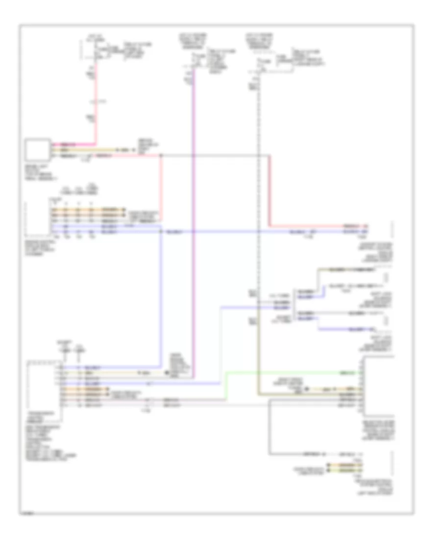
Shift Interlock Wiring Diagram, A/T for Audi A6 Quattro Premium 2014
List of elements for Shift Interlock Wiring Diagram, A/T for Audi A6 Quattro Premium 2014:
- (behind center of dash) g45
- (near engine control module on firewall) g645
- (right front side of center tunnel) g687
- 12a
- 2.0l turbo
- 3.0l sc
- 3.0l turbo diesel
- 4.0l turbo
- Brake light switch (top of brake pedal assembly)
- Comfort system central control module (right side of luggage compt)
- Computer data lines system
- Dsg transmission mechatronic (4.0l turbo) transmission control module (tcm) (except 4.0l turbo) (except 4.0l turbo: under transmission oil pan)
- Engine control module (ecm) (in left plenum chamber)
- Except 4.0l turbo
- Fuse 5a
- Fuse carrier
- Hot at all times
- Nca
- Relay & fuse panel a (in left plenum chamber e-box)
- Relay & fuse panel b (left end of dash)
- Relay & fuse panel f (right rear of luggage compt)
- Selector lever sensor system control module (base of shift lever assembly)
- Shift lock solenoid (base of shift lever assembly)
- T16c
- T17a
- T17b
- T17i
- T17o
- T32a
- T32g
- T4ca
- T91
- T94
- Transmission control module
- Vehicle electrical system control module (left end of dash)
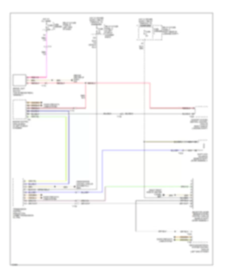
Shift Interlock Wiring Diagram, CVT for Audi A6 Quattro Premium 2014
List of elements for Shift Interlock Wiring Diagram, CVT for Audi A6 Quattro Premium 2014:
- (behind center of dash) g45
- (near engine control module on firewall) g645
- (right front side of center tunnel) g687
- 12a
- Brake light switch (top of brake pedal assembly)
- Comfort system central control module (right side of luggage compt)
- Computer data lines system
- Engine control module (ecm) (in left plenum chamber)
- Fuse 5a
- Fuse carrier
- Hot at all times
- Nca
- Relay & fuse panel a (in left plenum chamber e-box)
- Relay & fuse panel b (left end of dash)
- Relay & fuse panel f (right rear of luggage compt)
- Selector lever sensor system control module (base of shift lever assembly)
- Shiftlock solenoid (base of shift lever assembly)
- T16c
- T17a
- T17b
- T17i
- T17o
- T32a
- T32g
- T4ca
- T94
- Transmission control module (tcm) (under transmission oil pan)
- Vehicle electrical system control module (left end of dash)