SHIFT INTERLOCK
Park Brake Release Wiring Diagram for Audi Q5 Quattro 2009

List of elements for Park Brake Release Wiring Diagram for Audi Q5 Quattro 2009:
- Abs control module (left side of engine compt)
- Auto- hold
- Clutch position sensor (m/t)
- Computer data lines system
- Electro- mechanical parking brake control module
- Electro-mechanical parking brake button
- Fuse 30a
- Fuse 5a
- Fuse carrier 2
- Fuse carrier 3
- Fuse carrier 4
- G51 (behind right "d" pillar)
- Hot at all times
- Interior lights system
- Left parking brake motor
- Relay/ fuse panel sf (right side of luggage compt)
- Right parking brake motor
- Solid state
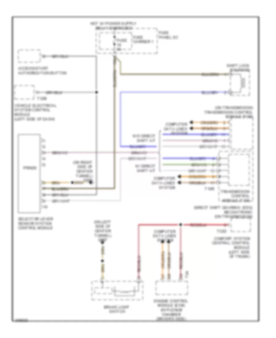
Shift Interlock Wiring Diagram for Audi Q5 Quattro 2009
List of elements for Shift Interlock Wiring Diagram for Audi Q5 Quattro 2009:
- (on left side of center tunnel) g687
- (on right side of center tunnel) g688
- (on transmission) transmission control module (tcm)
- 10a
- Access/start authorization button
- Brake light switch
- Comfort system central control module (left side of trunk)
- Computer data lines system
- Direct shift gearbox (dsg) mechatronic (on transmission)
- Engine control module (ecm) (in plenum chamber driver's side)
- Fuse 5a
- Fuse carrier 1
- Fuse panel sc
- Prnds
- Selector lever sensor system control module
- Shift lock solenoid
- T16r
- T32b
- T32d
- T94
- Transmission control module (tcm)
- Vehicle electrical system control module (left side of dash)
- W/ direct shift a/t
- W/o direct shift a/t