STARTING/CHARGING
Charging Wiring Diagram for Audi A6 Quattro Prestige 2014

List of elements for Charging Wiring Diagram for Audi A6 Quattro Prestige 2014:
- Battery
- Battery interrupt igniter
- Battery jump start terminal (right rear corner of engine compt)
- Battery monitoring control module (on battery)
- Computer data lines system
- Data bus on board diagnostic interface (below center of rear seat)
- Display unit
- Engine controls system
- Except 2.0l turbo
- G624
- G645 (near engine control module on firewall)
- Generator & voltage regulator
- Instrument cluster control module
- Main fuse carrier (in luggage compt on battery)
- Red
- Starter
- Suppressor (in right plenum chamber e-box)
- T17a
- T32
- Terminal 30 wire junction (in center plenum chamber)
- Voltage stabilizer (w/ start/ stop system) (in spare tire well)
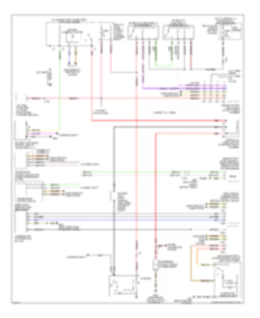
Starting Wiring Diagram for Audi A6 Quattro Prestige 2014
List of elements for Starting Wiring Diagram for Audi A6 Quattro Prestige 2014:
- (base of shift lever assembly) selector lever sensor system control module
- (in luggage compt on battery) main fuse carrier
- (on relay & fuse panel a) starter relay
- (on relay & fuse panel a) starter relay 2
- (right side of luggage compt) comfort system central control module
- 16a
- 3.0l sc
- 3.0l turbo diesel
- 4.0l turbo 2.0l
- 8 speed cvt 8 speed a/t
- Access/start authorization button
- Battery
- Battery interrupt igniter
- Battery jump start terminal (right rear corner of engine compt)
- Battery monitoring control module (on battery)
- Charging circuit
- Computer data lines system
- Direct shift gear box (dsg) mechatronic
- Engine control module (ecm) (in left plenum chamber)
- Except 2.0l turbo
- Fuse 40a
- Fuse 5a
- Fuse carrier
- G45 (behind center of dash)
- G624
- G645 (near engine control module on firewall)
- G687 (right front side of center tunnel)
- Power distribution system
- Prnds
- Red
- Relay & fuse panel a (in left plenum chamber e-box)
- Relay & fuse panel b (left end of dash)
- Start/stop mode button
- Start/stop mode ind lamp
- Starter
- Suppressor (in right plenum chamber e-box)
- T16c
- T17a
- T17b
- T32a
- T32c
- T32g
- T32i
- T91
- T94
- Terminal 30 wire junction (in center plenum chamber)
- Transmission control module
- Transmission control module (tcm) (under transmission oil pan)
- Vehicle electrical system control module (left end of dash)
- Voltage stabilizer (w/ start/ stop system) (in spare tire well)
- W/ direct shift
- W/ start/ stop system
- W/o direct shift