TRANSMISSION
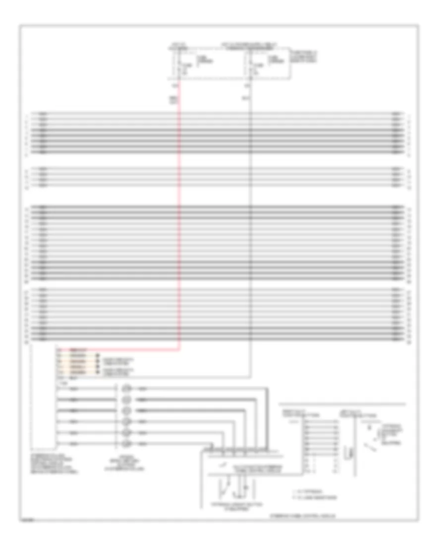
A/T Wiring Diagram (1 of 3) for Audi S4 2012

List of elements for A/T Wiring Diagram (1 of 3) for Audi S4 2012:
- (left rear of engine compt) g12
- (right rear of engine compt)
- 10a
- 12a
- Access/start authorization button
- Automatic transmission hydraulic pressure sensor 1
- Automatic transmission hydraulic pressure sensor 2
- Comfort system control module (right side of trunk)
- Computer data lines system
- Direct shift gearbox (dsg) transmission mechatronic
- Engine control module (ecm)
- Engine controls system
- Fuse 15a
- Fuse 5a
- Fuse carrier
- Fuse panel c
- G688 (right side of center tunnel)
- Gear position distance sensor 1
- Gear position distance sensor 2
- Gear position distance sensor 3
- Gear position distance sensor 4
- Hot at all times
- Interior lights system
- Nca
- Power distribution system
- Relay/fuse panel b (in plenum chamber electronics box)
- Selector lever sensor system control module (on shifter unit)
- T14h
- T14i
- T16r
- T17q
- T32b
- T32d
- T8al
- T94
- Temperature sensor (in control module)
- Transmission control module (tcm)
- Transmission park selector switch & shift lock solenoid (shift lock solenoid: on shifter unit)
- Vehicle electrical system control module (under left side of dash)
A/T Wiring Diagram (2 of 3) for Audi S4 2012
List of elements for A/T Wiring Diagram (2 of 3) for Audi S4 2012:
- (in steering column)
- 12a
- Air bag
- Computer data lines system
- Fuse 5a
- Fuse carrier
- Fuse panel d (lower right side of dash)
- Hot at all times
- Left multi- function buttons
- Mode
- Multi-function steering wheel control module
- Nca
- Right multi function buttons
- Slip ring
- Spiral return/
- Steering column electronic systems control module (on steering column behind steering wheel)
- Steering wheel control module
- T16f
- Tiptronic downshift button (if equipped)
- Tiptronic upshift button (if equipped)
- W/ lane assistance
- W/ tiptronic
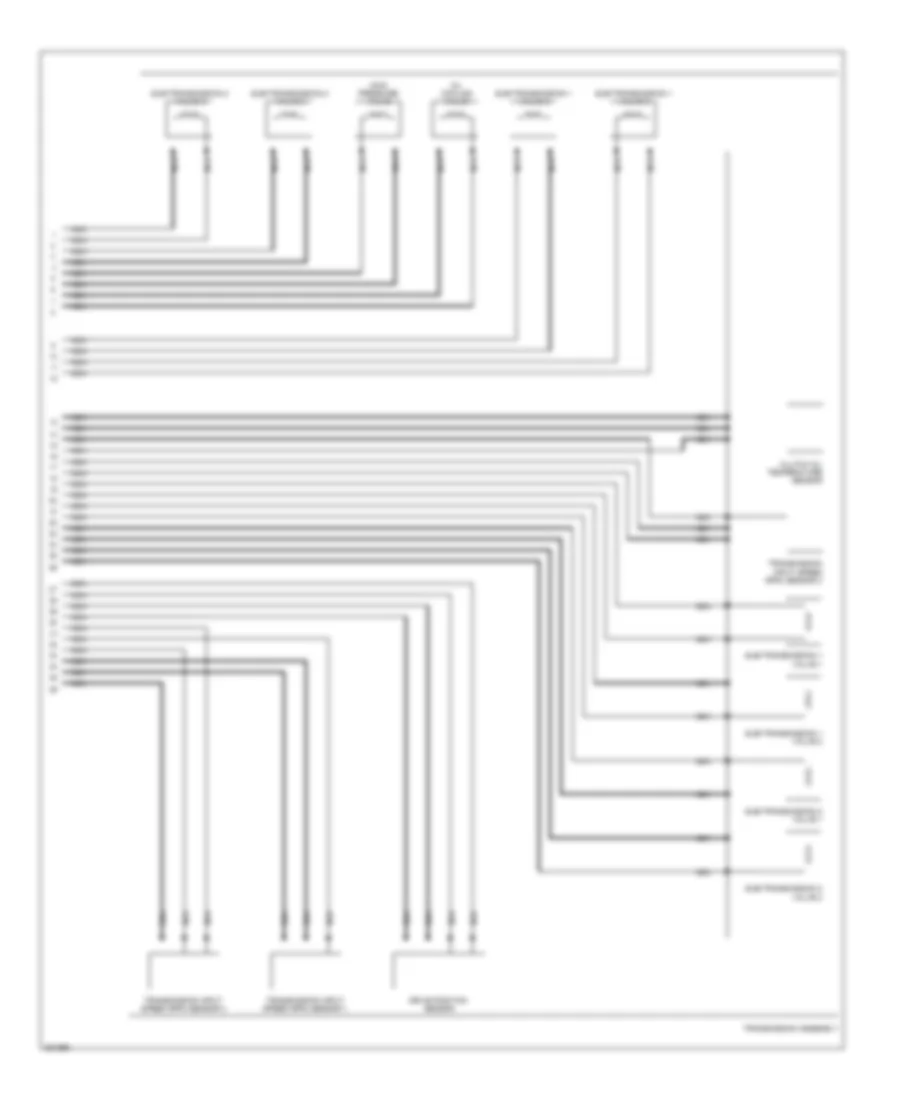
A/T Wiring Diagram (3 of 3) for Audi S4 2012
List of elements for A/T Wiring Diagram (3 of 3) for Audi S4 2012:
- Clutch oil temperature sensor
- Drive position sensor
- Main pressure valve
- Nca
- Oil cooling valve
- Sub-transmission 1 valve 1
- Sub-transmission 1 valve 2
- Sub-transmission 1 valve 3
- Sub-transmission 1 valve 4
- Sub-transmission 2 valve 1
- Sub-transmission 2 valve 2
- Sub-transmission 2 valve 3
- Sub-transmission 2 valve 4
- Transmission assembly
- Transmission input speed (rpm) sensor 1
- Transmission input speed (rpm) sensor 2
- Transmission input speed (rpm) sensor 3
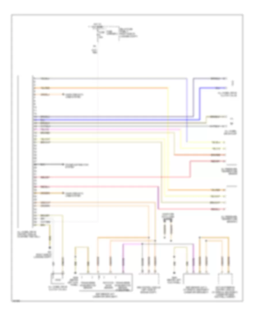
AWD Wiring Diagram for Audi S4 2012
List of elements for AWD Wiring Diagram for Audi S4 2012:
- Abs control module (left side of engine compt)
- Active steering control module (w/ special equipment) (under driver's footwell carpet)
- All wheel drive clutch valve
- All wheel drive clutch valve 2
- All wheel drive control module (in spare tire well)
- All wheel drive pump
- Computer data lines system
- Esp sensor unit (under driver's seat)
- Esp sensor unit 2 (w/ special equipment) (under driver's seat)
- Fuse 35a
- Fuse carrier 2
- G51 (right side of luggage compt)
- G639 (behind left kick panel)
- Hot at all times
- Oil pressure/ temperature sensor
- Oil pressure/ temperature sensor 2
- Power distribution system
- Relay/fuse panel f (right side of luggage compt)
- Rotation rate sensor
- Transverse acceleration sensor
- Transverse acceleration sensor (if equipped)