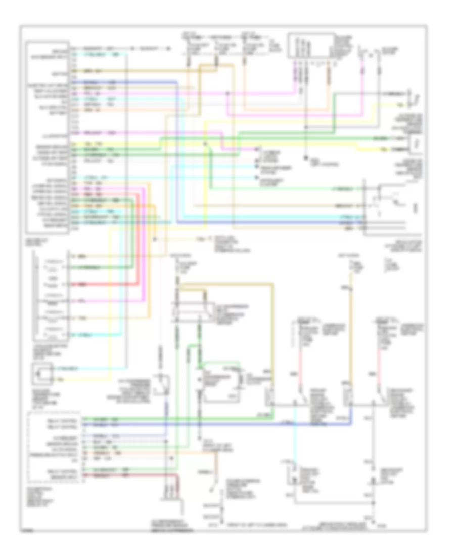
AIR CONDITIONING
Air Conditioning Wiring Diagrams for Cadillac Fleetwood Brougham 1995
List of elements for Air Conditioning Wiring Diagrams for Cadillac Fleetwood Brougham 1995:
- (behind compressor)
- (behind right headlamp
- (front of left
- (front of left cylinder head)
- +5v
- 40a
- A/c comp fuse 10a
- A/c compressor clutch
- A/c compressor clutch diode
- A/c compressor pressure cycling switch (right rear of engine compartment, on accumulator)
- A/c compressor relay (in underhood electrical center)
- A/c on signal
- A/c refrigerant pressure sensor
- A/c request
- Air mix motor (attached to left side of plenum)
- Attached to radiator support)
- Batt
- Battery
- Blower motor
- Blower motor control module (right i/p)
- Blw ctrl
- Blw motor fdbk
- Blw spd ctrl
- C1 a
- C10
- C11
- C12
- C13
- C14
- C15
- C16
- Ctrl sig
- Cylinder head)
- D10
- D11
- D12
- D13
- D14
- D15
- D16
- Data link connector (right of steering column)
- Def sol signal
- Dlc data link
- E/m signal
- Electric act drive
- G109
- G112
- G200 (left kickpad)
- Gen fuse 10a
- Ground
- Heater-a/c control
- Hot at all times
- Hot in run
- Htr sol signal
- Hvac bat fuse 10a
- Hvac ign fuse 10a
- Hvac mdl fuse 25a
- I/p fuse block
- Ignition
- Illumination
- Inside air temp
- Inside air temperature sensor (above glove box)
- Instrument cluster
- Interior lights system
- Logic
- Lower sol signal
- Nca
- Outside air temp
- Outside air temperature sensor (on hood latch support)
- Power steering pressure switch (near power steering unit)
- Powertrain control module (behind right side of i/p)
- Pressure switch input
- Primary clg fan maxi fuse
- Primary coolant fan motor (base and v03)
- Primary engine coolant fan relay (underhood electrical center) (base and v03)
- Rear defog
- Rear defogger system
- Recirc sol signal
- Red
- Relay control
- Second- ary clg fan maxi fuse
- Secondary coolant fan motor
- Secondary engine coolant fan relay (underhood electrical center)
- Sensor ground
- Sensor input
- Sun sensor input
- Sunload temperature sensor (top center of i/p)
- Tan
- Temp valve fdbk
- Underhood electrical center
- Upper sol signal
- Vacuum/electric solenoid (near center of i/p)
- Vf dim signal
 English