AIR CONDITIONING
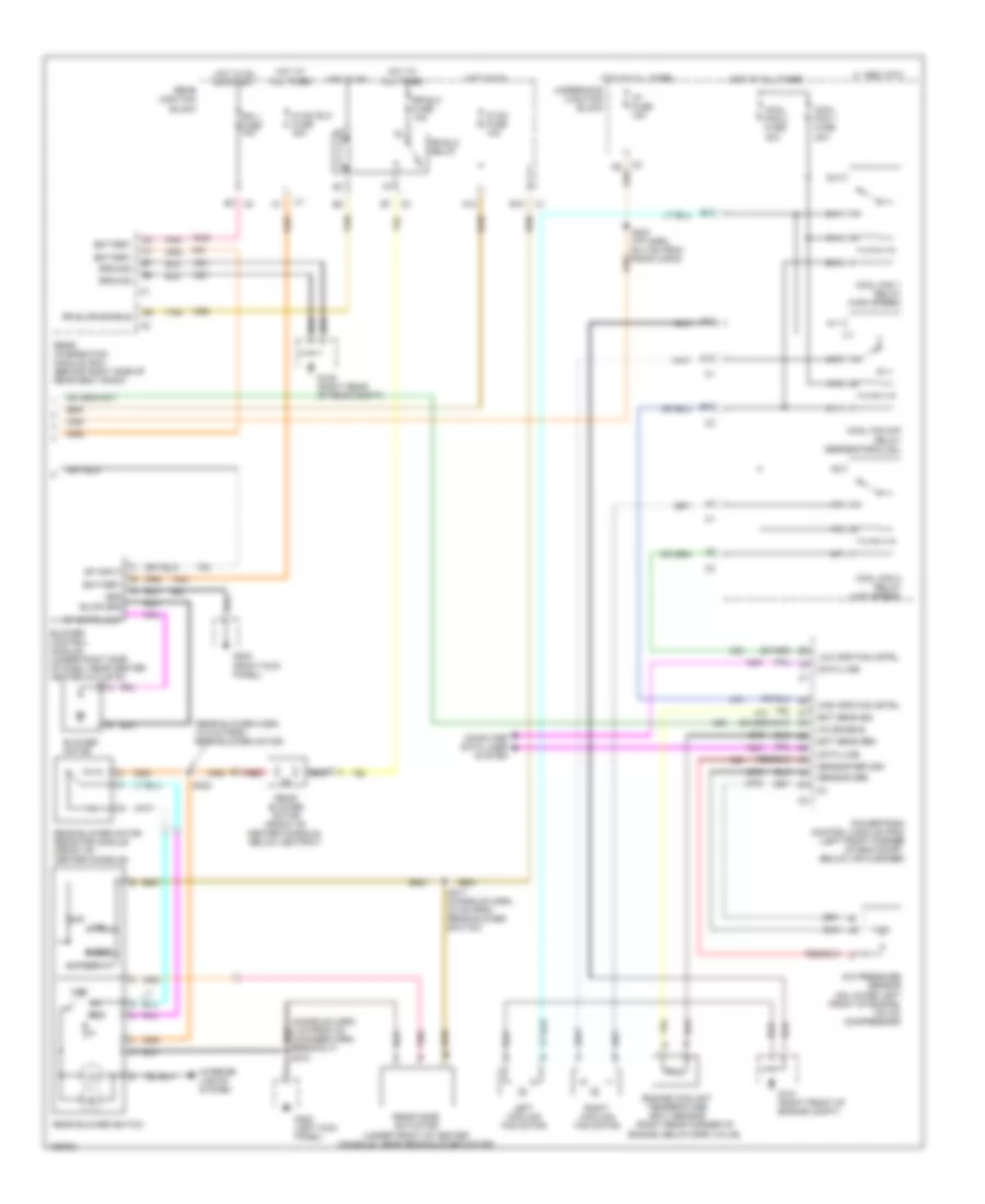
Automatic A/C Wiring Diagram (1 of 2) for Cadillac Seville STS 2000

List of elements for Automatic A/C Wiring Diagram (1 of 2) for Cadillac Seville STS 2000:
- (engine compt)
- (hvac harn, 73 cm from mode actuator)
- (hvac harn, 79.5 cm from mode actuator) s274
- (hvac harn, 89.5 cm from mode actuator)
- (i/p harn, 4 cm from lh sun load sens)
- (i/p harn, 8 cm from inst panel harness breakout)
- 1995 vftc c
- 5v ref feed
- 5v vlv signal
- A/c clu fuse 15a
- A/c clu relay
- A/c compressor clutch
- A/c low side temperature sensor (rear of eng compt, on a/c low side line)
- A10
- A11
- A12
- Acc
- Air inlet actuator (behind right side of dash, on hvac module)
- Air inlet vlv feed
- Air inlet vlv sig
- Air temp vlv feed
- Air temp vlv sig
- Ambient air temp sensor (center front of vehicle, near hood latch)
- Battery
- Blwr sp cntrl
- C11
- C3 b12
- Computer data lines system
- D11
- D16
- Dash integration module (dim) (on right side of dash, near blower motor)
- Data line
- Dim fuse 10a
- Driver air mix actuator (behind left side of dash, on hvac module)
- G203 (right kick panel)
- Ground
- Hot at all times
- Hot in on
- Hot in on or start
- Ign 3 rr fuse 10a
- Ign sw fuse 15a
- Ignition
- Ignition switch
- Inside air temperature sensor (behind left side of dash, left of steering column)
- Instrument panel integration module (ipm) (behind center of dash, above radio)
- Left a/c temp sensor (left side of dash, in a/c duct)
- Left inside air temp sensor (left side of dash, in a/c duct)
- Left sun load sensor (on left side of dash, in defrost grille)
- Lock
- Logic, 5v
- Mode actuator (behind left side of dash, on hvac module)
- Mode drive feed
- Motor return
- Passenger air mix actuator (behind right side of dash, on hvac module)
- Pnk
- Rear junction block
- Right a/c temp sensor (right side of dash, in a/c duct)
- Right inside air temp sensor (right side of dash, in a/c duct)
- Right sun load sensor (on right side of dash, in defrost grille)
- S203 (i/p harn, 55.5 cm from radio)
- S206
- S209
- S210 (i/p harn, 22 cm from left sun load sensor harn breakout)
- S275
- Sensor grd
- Solid state
- Start
- Tan
- Underhood junction block
Automatic A/C Wiring Diagram (2 of 2) for Cadillac Seville STS 2000
List of elements for Automatic A/C Wiring Diagram (2 of 2) for Cadillac Seville STS 2000:
- (console harn, 4 cm from cd changer harn breakout) s318
- (rear blower harn, 12.5 cm from rear blower motor)
- (right rear corner of
- 1995 vftc c
- A/c enable
- A/c pressure sensor (on lower left front of engine, on a/c compressor)
- A10
- A11
- B10
- Battery
- Blend
- Blower control module (under right side of dash, near center heater outlets)
- Blower motor
- Blwr grd
- C10
- C11
- Computer data lines system
- Cool fan 1 fuse 30a
- Cool fan 1 relay (high speed)
- Cool fan 2 fuse 30a
- Cool fan 2 relay (low speed)
- Cool fan s/p relay (series/parallel)
- D10
- Data line
- E10
- E11
- Ect sens grd
- Ect sens sig
- Engine coolant temperature (ect) sensor
- Engine, below egr valve)
- F11
- G10
- G101 (right front of engine compt)
- G105 (right rear of rear compt)
- G11
- G200 (left kick panel)
- G203 (right kick panel)
- Grd
- Ground
- High spd fan cntrl
- Hot at all times
- Hot in on
- Hot in on or start
- Hvac blo fuse 30a
- Hvac fuse 10a
- I/p fuse 15a
- Ign 1 fuse 10a
- Interior lights system
- Left cooling fan motor
- Low spd fan cntrl
- Lwr
- Med
- Off
- Pnk
- Powertrain control module (pcm) (left front corner of eng compt, below air cleaner)
- Rear blower motor (front of center console, below ashtray)
- Rear blower motor resistor module (front of center console)
- Rear blower switch
- Rear integration module (rim) (behind right side of rear seat back)
- Rear junction block
- Rear mode actuator (under front of center console, near rear blower motor)
- Red
- Right cooling fan motor
- Rr blo fuse 10a
- Rr blo relay
- Rr blwr enable
- S204 (i/p harn, 64.5 cm from radio conn)
- S317 (console harn, 33 cm from rear blower switch)
- S322
- Sensor grd
- Sensor return
- Sp cntrl out
- Sp input
- Tan
- Underhood junction block
- Upper
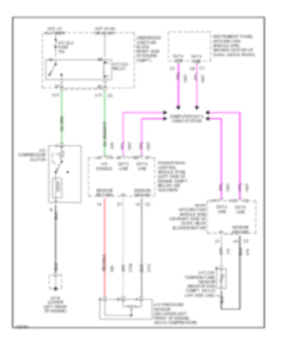
Compressor Wiring Diagram for Cadillac Seville STS 2000
List of elements for Compressor Wiring Diagram for Cadillac Seville STS 2000:
- A/c clu fuse 15a
- A/c clu relay
- A/c compressor clutch
- A/c enable
- A/c pressure sensor (on lower left front of engine, on a/c compressor)
- A11
- A12
- C1 c8
- C11
- Computer data lines system
- Dash integration module (dim) (on right side of dash, near blower motor)
- Data line
- G110 (lower left front of engine)
- Hot at all times
- Hot in on or start
- Instrument panel integration module (ipm) (behind center of dash, above radio)
- Powertrain control module (pcm) (left side of engine compt, below air cleaner)
- Sensor ground
- Sensor return
- Underhood junction block (right side of engine compt)