AIR CONDITIONING
Automatic A/C Wiring Diagram (1 of 2) for Cadillac XLR 2004

List of elements for Automatic A/C Wiring Diagram (1 of 2) for Cadillac XLR 2004:
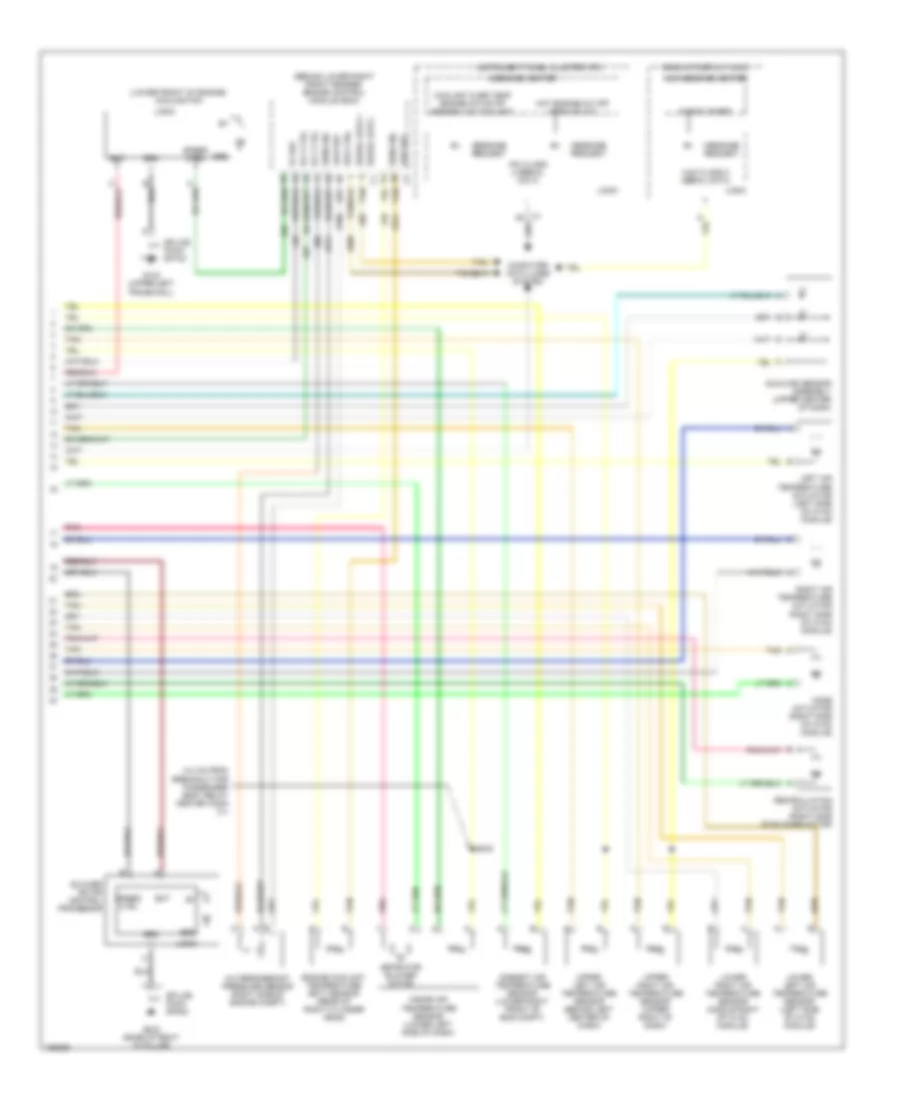
Automatic A/C Wiring Diagram (2 of 2) for Cadillac XLR 2004
List of elements for Automatic A/C Wiring Diagram (2 of 2) for Cadillac XLR 2004:
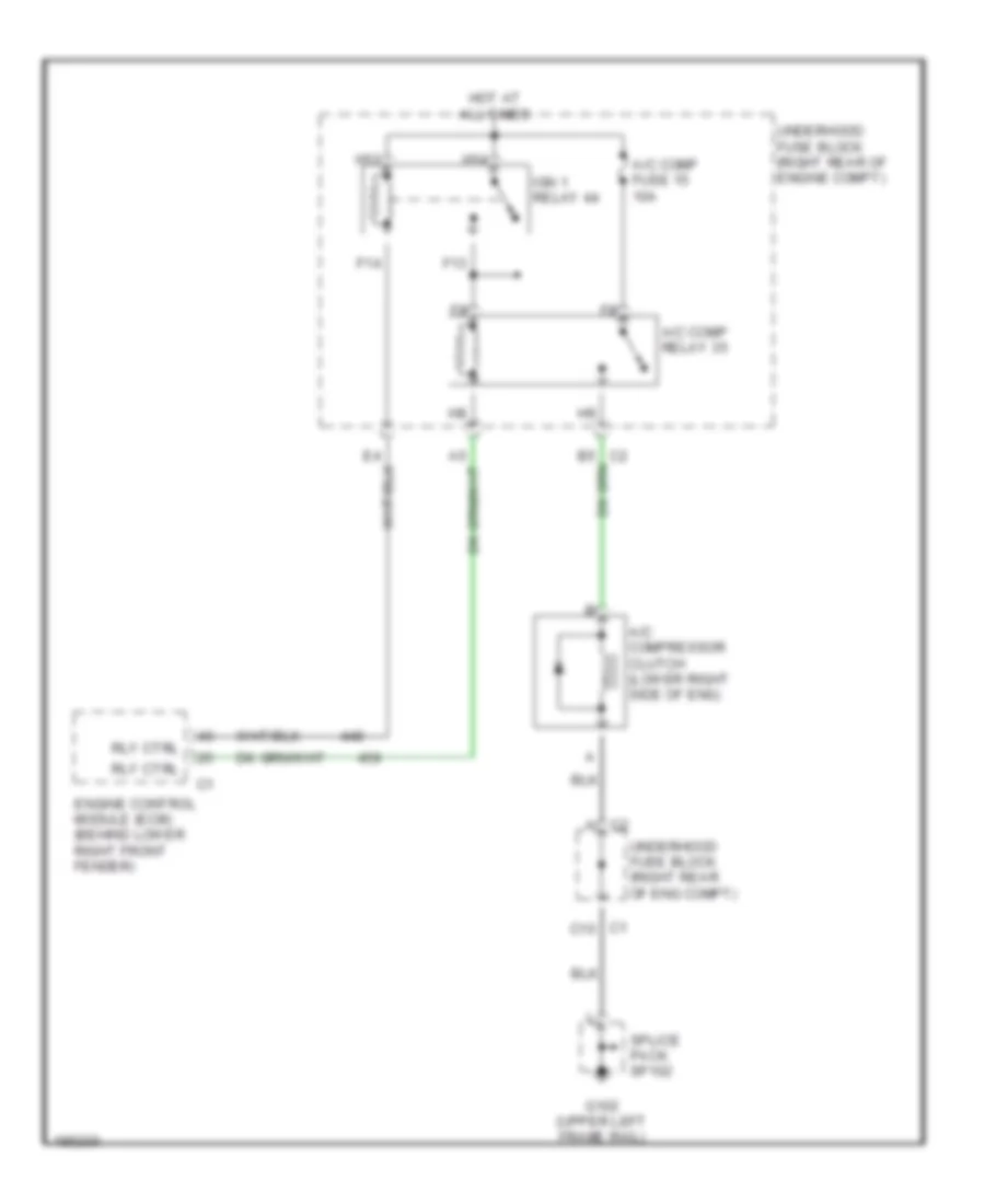
Compressor Wiring Diagram for Cadillac XLR 2004
List of elements for Compressor Wiring Diagram for Cadillac XLR 2004: