ANTI-LOCK BRAKES
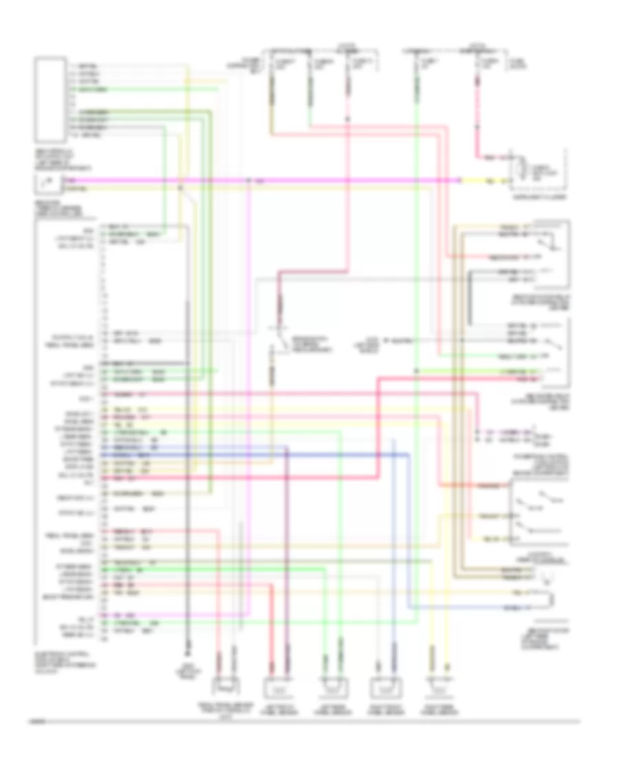
Anti-lock Brake Wiring Diagrams for Jeep Cherokee Country 1994
List of elements for Anti-lock Brake Wiring Diagrams for Jeep Cherokee Country 1994:
- (left rear of engine compartment)
- Abs diode (taped in harness near controller)
- Abs hydraulic actuation unit (left rear of engine compartment)
- Abs pump motor
- Abs pump motor relay (in power distribution center)
- Abs system relay (in power distribution center)
- Accel sens
- Accel sens 2
- Accel sw 1
- B116
- B210
- B219
- B220
- B234
- B245
- B248
- B249
- B251
- B254
- B258
- Boost pres
- Boost pres return
- Brake switch (on brake pedal bracket)
- Buss +
- Buss -
- Ccd +
- Ccd -
- Check anti-lock ind
- Decay mod vlv
- Electronic control module (ecm) (right side of steering column)
- Fuse 13 20a
- Fuse 7 2a
- Fuse 9 10a
- Fuse block
- Fuse f7 30a
- Fuse f9 40a
- G switch (rear of console)
- G100 (left side shield)
- G200 (left kick panel)
- Gnd
- Hot at all times
- Hot in run
- Hot in start or run
- Ign (12 volts)
- Instrument cluster
- L fnt decay vlv
- L fnt iso vlv
- L fnt sens +
- L fnt sens -
- L rear sens +
- L rear sens -
- L50
- Left front wheel sensor
- Left rear wheel sensor
- Pedal travel sens
- Pedal travel sensor (part of hydraulic unit)
- Pnk
- Power distribution box
- Powertrain control module (pcm) (left front of engine compartment)
- Pump rly coil b-
- Rear iso vlv
- Red
- Right front wheel sensor
- Right rear wheel sensor
- Rly
- Rt fnt decay vlv
- Rt fnt iso vlv
- Rt fnt sens +
- Rt fnt sens -
- Rt rear sens +
- Rt rear sens -
- Sol (12 volts)
- Stop lp sig
- Tan
 English