ANTI-LOCK BRAKES
Anti-lock Brake Wiring Diagrams for Jeep Cherokee Sport 1996
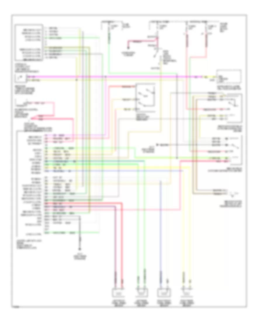
List of elements for Anti-lock Brake Wiring Diagrams for Jeep Cherokee Sport 1996:
- A10
- A11
- A12
- Abs diode (taped in harness near controller anti-lock brake)
- Abs main relay (in power distribution center)
- Abs main rly ctrl
- Abs main rly out
- Abs pump motor (bottom of left fender side shield)
- Abs pump motor relay (in power distribution center)
- Abs pump rly ctrl
- Abs warn lp
- Abs warning lamp
- B10
- B11
- B116
- B12
- B13
- B14
- B15
- B16
- B17
- B18
- B205
- B207
- B233
- B234
- B235
- B236
- B245
- B248
- B249
- B251
- B254
- B515
- B516
- B517
- C151
- C235
- C27 sci
- Combination flasher
- Controller anti-lock brake (right side of steering column)
- D21
- Data link connector (bottom of knee bolster, left of steering column)
- Fuse 14 30a
- Fuse 2 20a
- Fuse 5 40a
- Fuse 7 2a
- Fuse block
- G sw 1
- G sw 2
- G switch (below left rear seat)
- G switch gnd
- G117 (right rear of engine)
- Gnd
- Hot at all times
- Hot in run
- Hydraulic control unit (left rear of engine compartment)
- Ignition
- Instrument cluster (telltale connector)
- L50
- Left front wheel speed sensor
- Left rear wheel speed sensor
- Lf dump vlv ctrl
- Lf iso vlv ctrl
- Lf sens +
- Lf sens -
- Lr sens +
- Lr sens -
- Pnk
- Power distri- bution box
- Powertrain control module (left fender side shield)
- Pump mtr rly out
- Rear dump vlv ctrl
- Rear iso vlv ctrl
- Red
- Rf dump vlv ctrl
- Rf iso vlv ctrl
- Rf sens +
- Rf sens -
- Right front wheel speed sensor
- Right rear wheel speed sensor
- Rr sens +
- Rr sens -
- Sci transmit
- Stop lamp switch (top of brake pedal arm)
- Stop lp sig
- Transmit
 English