ANTI-LOCK BRAKES
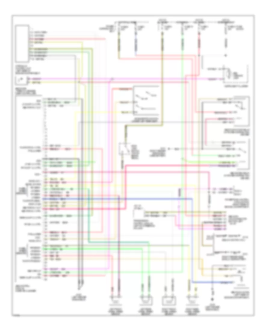
Anti-lock Brake Wiring Diagrams for Jeep Grand Cherokee Laredo 1995
List of elements for Anti-lock Brake Wiring Diagrams for Jeep Grand Cherokee Laredo 1995:
- (below ignition coil)
- (right fender side shield, near battery)
- (under left rear seat)
- 4.0 a/t
- 4.0l w/ a/t only
- 5.2l & 4.0 m/t
- Abs control module (near air cleaner)
- Abs data link connector (bottom left
- Abs diode (taped in harness near controller)
- Abs pump motor (left rear of engine compartment)
- Abs pump motor relay (in power distribution center)
- Abs pwr rly ctrl
- Abs pwr rly out
- Abs system relay (in power distribution center)
- Abs warn lp
- Abs warning lamp
- Accel sw 1
- Accel sw 2
- Accel sw gnd
- Acceleration switch
- B116
- B210
- B219
- B220
- B243
- B245
- B248
- B249
- B251
- B254
- B41
- B42
- B43
- Bus (+)
- Bus (-)
- Ccd +
- Ccd -
- D82
- Fuse 15 3a
- Fuse 2 15a
- Fuse 21 15a
- Fuse 3 10a
- Fuse 7 40a
- Fuse 9 20a
- Fuse block
- G100 (left fender side shield)
- G101
- G101 (right fender side shield, near battery)
- G119
- Gnd
- Hot at all times
- Hot in run
- Hot in start or run
- Hydraulic control unit (left rear of engine compartment)
- Ign
- Instrument cluster
- L50
- Left front wheel speed sensor
- Left rear wheel speed sensor
- Lf dump vlv ctrl
- Lf iso vlv ctrl
- Lf sens +
- Lf sens -
- Lr sens +
- Lr sens -
- Of i/p)
- Pnk
- Power distribution box
- Powertrain control module (pcm) (right rear of engine compartment)
- Pts jumper
- Pump/mtr rly ctrl
- Pump/mtr sens +
- Pump/mtr sens -
- Rear dump vlv ctrl
- Rear inlet vlv ctrl
- Red
- Rf dump vlv ctrl
- Rf iso vlv ctrl
- Rf sens +
- Rf sens -
- Right front wheel speed sensor
- Right rear wheel speed sensor
- Rr sens +
- Rr sens -
- Stop lamp switch (top of brake pedal)
- Stop lp sig
- Tan
- Transmission control module (left of streering column)
- Wheel speed sensors
 English