BODY CONTROL MODULES
Dash Integration Module Wiring Diagram for Cadillac CTS V 2007

List of elements for Dash Integration Module Wiring Diagram for Cadillac CTS V 2007:
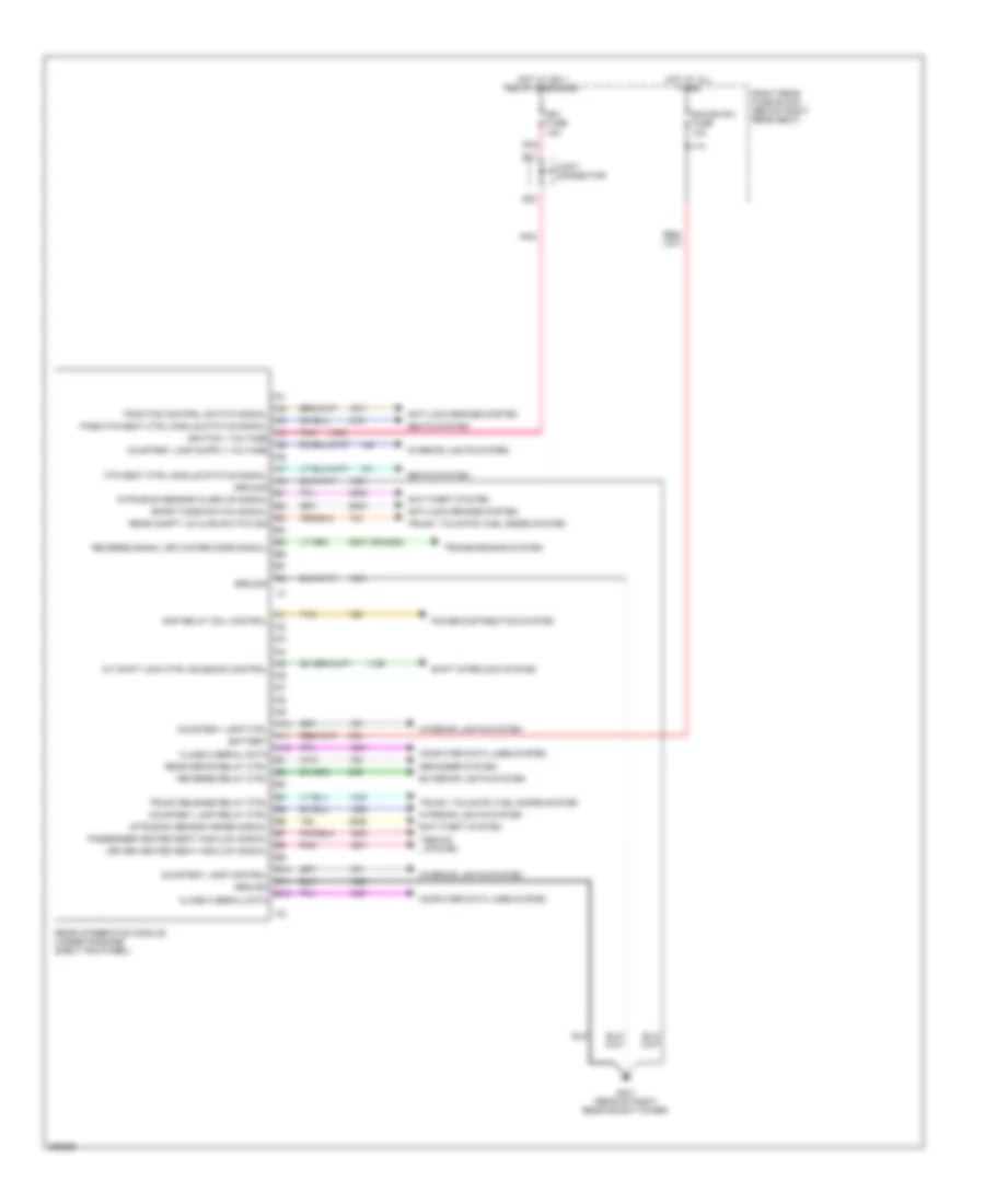
Rear Integration Module Wiring Diagram for Cadillac CTS V 2007
List of elements for Rear Integration Module Wiring Diagram for Cadillac CTS V 2007: