ENGINE PERFORMANCE
5.7L
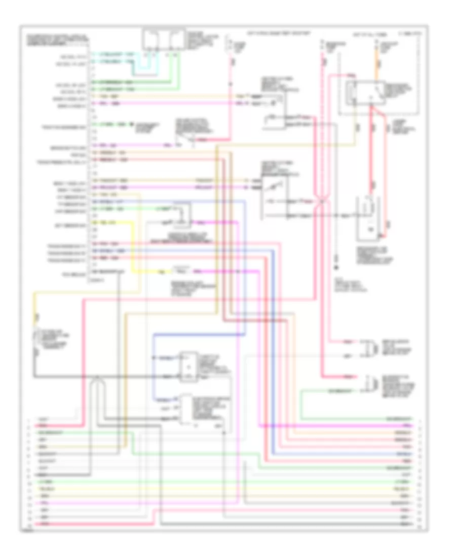
5.7L (VIN P), Engine Performance Wiring Diagrams (1 of 3) for Cadillac Fleetwood Brougham 1995

List of elements for 5.7L (VIN P), Engine Performance Wiring Diagrams (1 of 3) for Cadillac Fleetwood Brougham 1995:
- high res
- (rear of right cylinder, below
- 5 volts ref
- A/c clutch status
- A/c compressor relay
- A/c request sig
- Air conditioning system
- Air pump relay ctrl
- Battery
- C 1995 vftc
- Central control module (in rear compartment, behind rear seat)
- Coil
- Conn a
- Conn b
- Coolant fan relays
- Cruise control, speedo, radio, warning alarm & cent ctrl module
- Dist ignition feed
- Dist ref low sig
- Distributor
- Egr solenoid ctrl
- Eng oil level sens sig
- Engine oil level sensor (left side of engine oil pan)
- Exhaust manifold)
- Fuel enable sig
- Fuel injector #1
- Fuel injector #2
- Fuel injector #3
- Fuel injector #4
- Fuel injector #5
- Fuel injector #6
- Fuel injector #7
- Fuel injector #8
- Fuel pump relay ctrl
- G110
- G110 (rear of right cylinder, below exhaust manifold)
- Ground
- High resolution sig
- Hot at all times
- Hot in run or start
- Hot in run, bulb test or start
- Idle speed control power steering pressure switch (in power steering line near power unit)
- Ign
- Ignition
- Ignition ctrl
- Inj #1 ctrl
- Inj #2 ctrl
- Inj #3 ctrl
- Inj #4 ctrl
- Inj #5 ctrl
- Inj #6 ctrl
- Inj #7 ctrl
- Inj #8 ctrl
- Inj 1 fuse 10a
- Inj 2 fuse 10a
- Instrument cluster system
- Interface circuit
- Low oil ind ctrl
- Low res
- Low resolution sig
- Maf sensor sig
- Mass air flow sensor (between air cleaner and intake resonator)
- Optical sensor
- Pcm ground
- Pcm/fuel pump fuse 15a
- Pcm/ign fuse 10a
- Pnk
- Powertrain control module (forward of left wheelhouse, under air cleaner)
- Pri cool fan rel ctrl
- Psp switch in
- Red
- Ref low
- Sec cool fan rel ctrl
- Sensor ground
- Spark plugs
- Tach output
- Tcc temp switch (in trans oil cooler inlet pipe)
- Tcc temp switch sig
- Trans 1-2 shift ctrl
- Trans 2-3 shift ctrl
- Trans 3-2 shift ctrl
- Under- hood electrical center
- Vehicle speed sensor (left rear of transmission)
- Vss ground
- Vss out
- Vss signal
5.7L (VIN P), Engine Performance Wiring Diagrams (2 of 3) for Cadillac Fleetwood Brougham 1995
List of elements for 5.7L (VIN P), Engine Performance Wiring Diagrams (2 of 3) for Cadillac Fleetwood Brougham 1995:
- (right rear of engine compartment)
- Air pump fuse 20a
- Bank 1 h02s low
- Bank 1 ho2s hi
- Bank 2 ho2s hi
- Bank 2 ho2s low
- Brake switch sig
- C 1995 vftc
- Chime fuse 10a
- Conn c
- Cruise control release switch (on brake pedal support bracket)
- D pnk
- Ect sensor sig
- Egr solenoid valve (top of engine behind inj #7)
- Electronic brake and traction control module (left side of engine compartment)
- Emissions fuse 10a
- Engine coolant temperature sensor (right front of engine)
- Evaporative emission canister purge solenoid valve (top of engine behind inj #4)
- G110 (rear of right cylinder, below exhaust manifold)
- Heated oxygen sensor 1 (bank 1, right exhaust manifold)
- Heated oxygen sensor 2 (bank 2, left exhaust manifold)
- Hot at all times
- Hot in run, bulb test or start
- Iac coil "a" hi
- Iac coil "a" low
- Iac coil "b" hi
- Iac coil "b" low
- Iat sensor sig
- Idle air control motor (right front of throttle body)
- Instrument cluster system
- Intake air temperature sensor (air cleaner assembly)
- Manifold absolute pressure sensor
- Map sensor sig
- Nca
- Pcm ground
- Pnk
- Pnp sig
- Powertrain control module (forward of left wheelhouse, under air cleaner)
- Red
- Red a
- Red b
- Secondary air injection pump assembly (lower right side of engine block)
- Secondary air injector (air) pump relay
- Tan
- Throttle position sensor (attached to throttle body) a
- Tp sensor sig
- Traction engaged sig
- Trans press ctrl sol hi
- Trans range sig "a"
- Trans range sig "b"
- Trans range sig "c"
- Under- hood electrical center
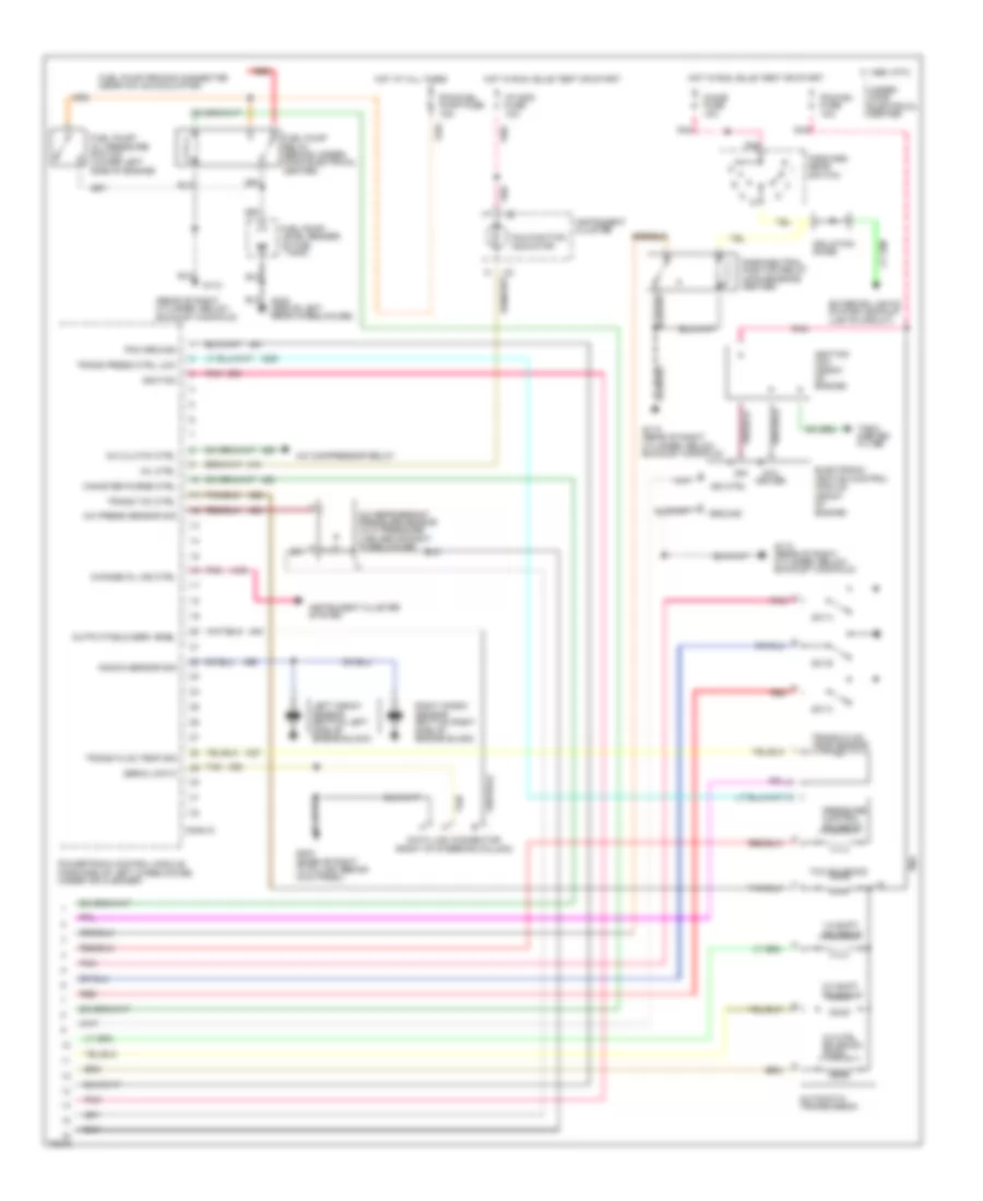
5.7L (VIN P), Engine Performance Wiring Diagrams (3 of 3) for Cadillac Fleetwood Brougham 1995
List of elements for 5.7L (VIN P), Engine Performance Wiring Diagrams (3 of 3) for Cadillac Fleetwood Brougham 1995:
- (rear of right cylinder, below exhaust manifold)
- 1-2 shift solenoid
- 2-3 shift solenoid
- 3-2 ctrl solenoid (pwm)
- A/c clutch ctrl
- A/c compressor relay
- A/c press sensor sig
- A/c refrigerant pressure sensor (in hi pressure line above right wheelhouse)
- Automatic transmission
- C 1995 vftc
- Canister purge ctrl
- Change oil ind ctrl
- Chime fuse 10a
- Coil driver
- Conn d
- Data link connector (right of steering column)
- Electronic ignition control module (front of engine)
- Exterior lights system (backup lights circuit)
- Forward gear switch
- Fuel pump priming connector (near a/c accumulator)
- Fuel pump relay (behind under- hood electrical center)
- Fuel pump/ level sender (in fuel tank)
- Fuel pump/ oil pressure switch (lower left side of engine)
- G110
- G110 (rear of right cylinder, below exhaust manifold)
- G203 (base of right "a" pillar, behind kick panel)
- G402 (above left rear wheelhouse)
- Ground
- Hot at all times
- Hot in run, bulb test or start
- I/p indc fuse 10a
- Ign
- Ign ctrl
- Ignition
- Ignition coil (front of engine)
- Instrument cluster
- Instrument cluster system
- Isolation diode
- Knock sensor sig
- Left knock sensor (bottom left side of engine block)
- Malfunction indicator
- Mil ctrl
- Output/field serv enbl
- Park/neutral position relay (convenience center)
- Pcm ground
- Pcm/fuel pump fuse 15a
- Pcm/ign fuse 10a
- Pnk
- Powertrain control module (forward of left wheelhouse, under air cleaner)
- Pressure control solenoid
- Red
- Right knock sensor (bottom right side of engine block)
- Serial data
- Sw a
- Sw b
- Sw c
- Tach- ometer filter
- Tan
- Tan m
- Tcc solenoid
- Trans fluid temp sensor
- Trans fluid temp sig
- Trans press ctrl low
- Trans tcc ctrl
- Under- hood electrical center