POWER DISTRIBUTION
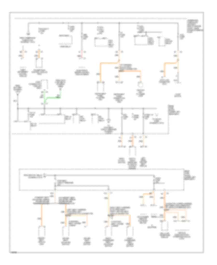
Power Distribution Wiring Diagram (1 of 5) for Cadillac Seville SLS 2004

List of elements for Power Distribution Wiring Diagram (1 of 5) for Cadillac Seville SLS 2004:
- (in front bank ignition coil jumper harness, 13.5 cm from ignition coil/module 2) s132
- (in front bank ignition coil jumper harness, 13.5 cm from ignition coil/module 7) s142
- (on right side of engine compt, near power steering pump) underhood fuse block
- A/c clu fuse 15a
- A/c clu relay
- Accy fuse 15a
- Accy relay
- Air ctrl vlu relay
- Air pump fuse 50a
- Automatic transaxle
- Battery
- Coil mdl fuse 20a
- Cruise control module (ccm)
- Cruise fuse 10a
- Drl fuse 15a
- Drl relay
- E10
- Evaporative emissions (evap) canister purge solenoid
- Fog fuse 10a
- Fog lp relay
- From acc relay (diagram 1 of 5)
- From underhood fuse block (diagram 1 of 5)
- Fuel injectors
- G104
- Generator
- Hdlp hi bm relay
- Hdlp lo bm relay
- Heated oxygen sensor (ho2s) (bank 1, sensor 2)
- Heated oxygen sensor (ho2s) (bank 2, sensor 1)
- Ign 1 fuse 10a
- Ign 1 relay
- Ignition coil module 1
- Ignition coil module 2
- Ignition coil module 3
- Ignition coil module 4
- Ignition coil module 5
- Ignition coil module 6
- Ignition coil module 7
- Ignition coil module 8
- Inj 1 fuse 10a
- Inj 2 fuse 10a
- L10
- M11
- Mass air flow (maf) sensor
- Nca
- Outside moisture sensor (if equipped)
- Oxy sen fuse 10a
- P11
- Pcm ign fuse 10a
- Pnk
- Powertrain control module (pcm)
- Red
- Secondary air injection (air) pump relay
- Secondary air injection (air) solenoid
- Splice pack sp104 (right side of engine compt, below fuse block)
- Start 1 relay
- Start circuit breaker 30a
- Starter solenoid
- To air pump fuse (diagram 1 of 5)
- To c/ltr fuse (diagram 3 of 5)
- To ign 1 relay (diagram 1 of 5)
- To ignition switch (connector c1, pin b) (diagram 4 of 5)
- To ignition switch (connector c1, pin c) (diagram 4 of 5)
- To park lamp relay (diagram 2 of 5)
- To pcm batt fuse (diagram 2 of 5)
- To rear fuse block (diagram 2 of 5)
- Trans fuse 10a
- Underhood fuse block (on right side of engine compt, near power steering pump)
- V10
- Windshield wiper motor
- Windshield wiper/ washer switch
- Wsw fuse 30a
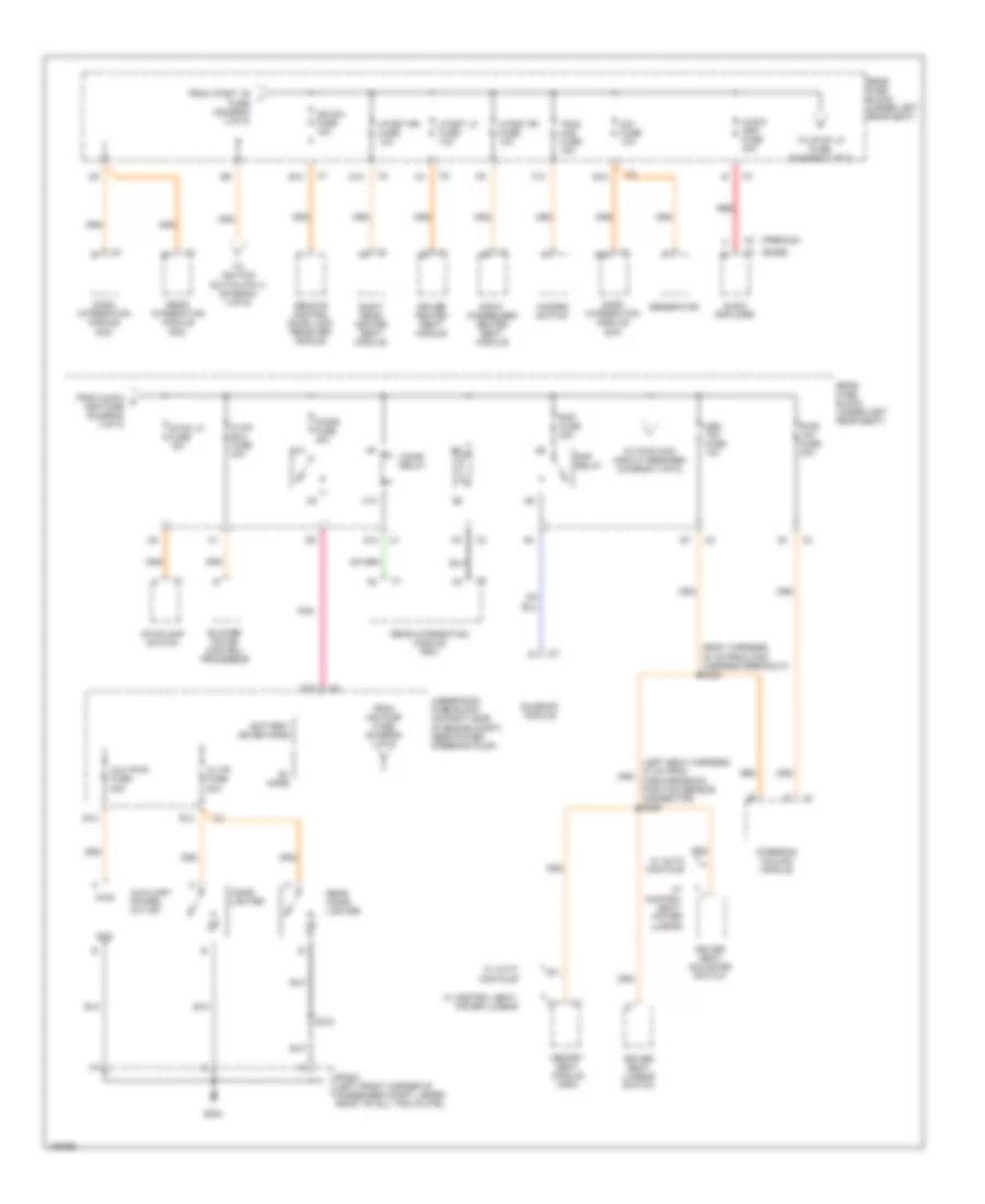
Power Distribution Wiring Diagram (2 of 5) for Cadillac Seville SLS 2004
List of elements for Power Distribution Wiring Diagram (2 of 5) for Cadillac Seville SLS 2004:
- (in onstar jumper harness, between c345 & breakout of vehicle interface unit) s361
- (left seat harness, 42 cm from left lumbar switch connector) s312
- (right seat harness, 57 cm from right front heated seat module connector) s314
- A10
- A15
- A16
- Abs fuse 50a
- Aldl fuse 10a
- Audio fuse 15a
- Cd changer remote playback device
- Cellular telephone module
- Cool fan 1 fuse 30a
- Cool fan 1 relay (low)
- Cool fan 2 fuse 30a
- Cool fan 2 relay (high)
- Cool fan s/p relay
- Dash integration module (dim)
- Data link connector (dlc)
- Digital radio receiver (w/ digital system s-band)
- Driver seat adjuster switch
- Driver seat lumbar switch
- E12
- E16
- Electronic brake control module (ebcm)
- F12
- From battery (diagram 1 of 5)
- From hdlp hi bm relay (diagram 1 of 5)
- From rr ctsy relay w (diagram 2 of 5)
- From underhood fuse block (diagram 1 of 5)
- Front passenger seat adjuster switch
- Front passenger seat lumbar switch
- Frt ctsy relay
- G10
- G11
- Horn fuse 15a
- Horn relay
- Htdst lr fuse 10a
- I/p fuse 10a
- If equipped
- Ignition key cylinder lamp
- Instrument panel cluster (ipc)
- Instrument panel integration module (ipm)
- Int lp fuse 10a
- Int lp relay
- L11
- L12
- Left rear heated seat module
- M11
- Memory seat module (msm)
- Nav fuse 10a
- Nca
- Pcm batt fuse 10a
- Powertrain control module (pcm)
- Prk lp relay
- Pwr seat circuit breaker 30a
- Radio
- Radio (w/ nav- igation)
- Rear fuse block (under left rear seat)
- Red
- Rr ctsy relay
- S10
- S11
- Sdar fuse 5a
- Theft deterrent control module
- To ign sw fuse (diagram 3 of 5)
- To pwr seat circuit breaker (diagram 2 of 5)
- Underhood fuse block (on right side of engine compt, near power steering pump)
- Valet switch
- Vehicle communication interface module (vcim)
- W/control seat, power lumbar
- W/memory seat adjuster, mirror power driver personalization
- W/o memory seat adjuster, mirror power driver personalization
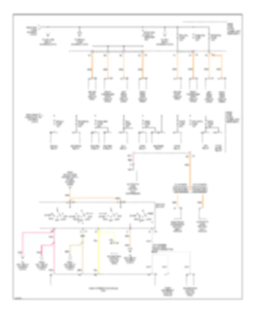
Power Distribution Wiring Diagram (3 of 5) for Cadillac Seville SLS 2004
List of elements for Power Distribution Wiring Diagram (3 of 5) for Cadillac Seville SLS 2004:
- (base)
- (body harness, 40 cm from c300 harness breakout) s302
- (left seat harness, 47 cm from
- (premium)
- A10
- A12
- Audio amp fuse 30a
- Audio amplifier
- Aux pwr fuse 20a
- Auxiliary power outlet
- B+ mode
- B11
- B12
- Battery saver mode
- Blower motor control processor
- C/ltr fuse 20a
- C10
- Cigar fuse 40a
- Cigar lighter
- Cigar relay
- D10
- D11
- D12
- Dash integration module (dim)
- Dim fuse 10a
- Driver heated seat module
- Driver seat adjuster switch
- Driver seat lumbar switch
- E10
- E12
- F12
- Forward/back position sensor connector) s326
- From air pump fuse (diagram 1 of 5)
- From audio k amp fuse (diagram 3 of 5)
- From htdst lr i fuse (diagram 2 of 5)
- G200
- Generator
- Gnd
- Hazard switch
- Htdst lf fuse 10a
- Htdst rf fuse 10a
- Htdst rr fuse 10a
- Hvac blo fuse 30a
- Ign sw fuse 15a
- Mem t&t fuse 10a
- Memory seat module (msm)
- Pnk
- Pwr
- Pwr t&t fuse 30a
- Rap fuse 20a
- Rap relay
- Rear cigar lighter
- Rear fuse block (under left rear seat)
- Rear integration module (rim)
- Red
- Remote control door lock receiver (rcdlr)
- Right passenger heated seat module
- Right rear heated seat module
- S318
- Sp200 (left front corner of passenger compt, under front of sill trim plate)
- Steering column module
- Stop lp fuse 15a
- Stoplamp switch
- Sunroof module
- To ignition switch pin a (diagram 4 of 6)
- To pwr wdo circuit breaker (diagram 4 of 5)
- To stop lp fuse (diagram 3 of 5)
- Tsig/ haz fuse 15a
- Underhood fuse block (on right side of engine compt, near power steering pump)
- W/ auto contour
- W/ control seat, power lumbar
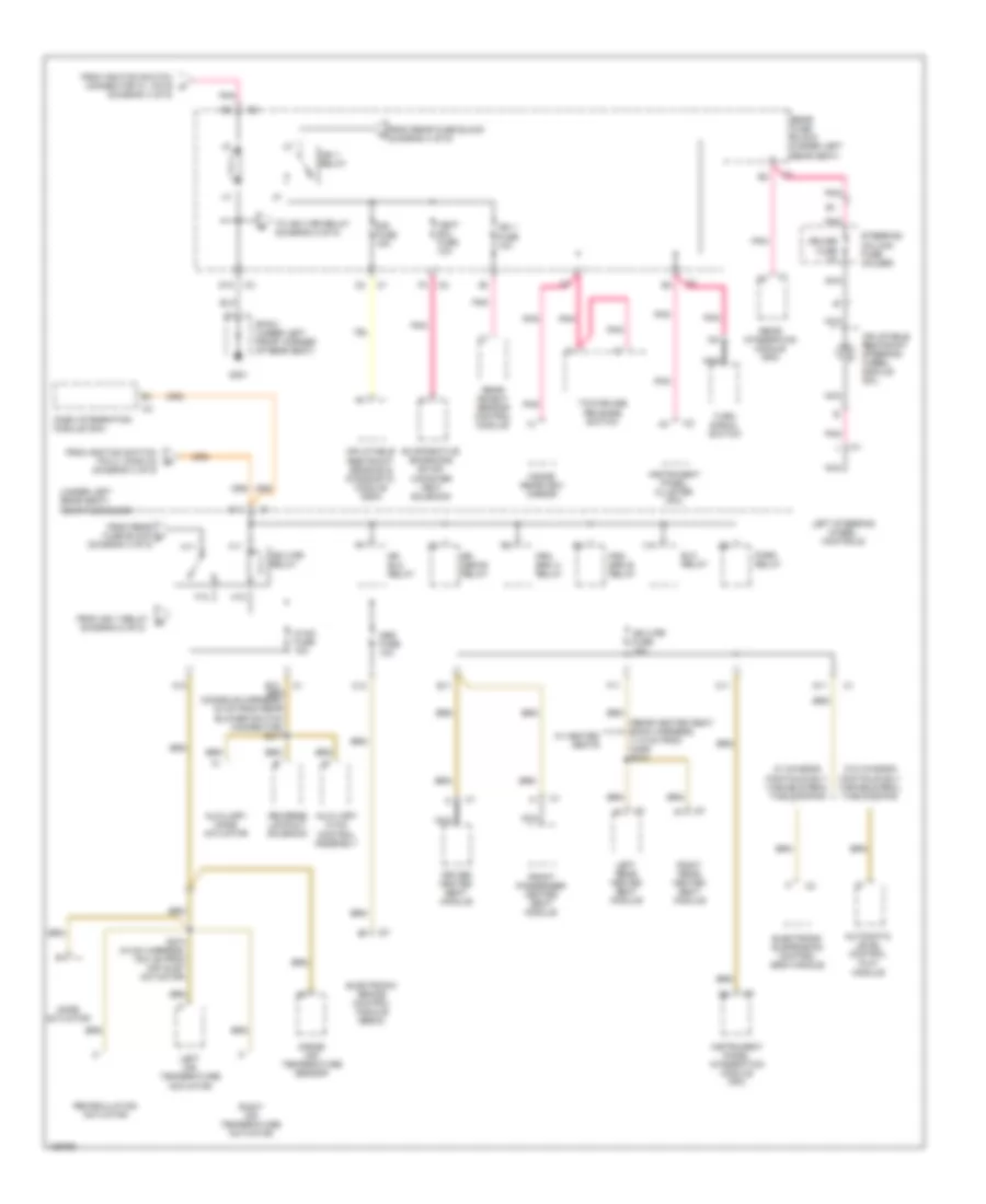
Power Distribution Wiring Diagram (4 of 5) for Cadillac Seville SLS 2004
List of elements for Power Distribution Wiring Diagram (4 of 5) for Cadillac Seville SLS 2004:
- (diagram 4 of 5)
- (i/p harness, 94.5 cm from radio connector) s205
- (under left rear seat)
- Acc
- Automatic level control (alc) compressor
- Automatic level control (alc) module
- B10
- Body fuse 15a
- Dash integration module (dim)
- Driver door module (ddm)
- Drv mdl fuse 10a
- Elc fuse 30a
- Elc relay
- Electronic suspension control (esc) module
- F/pmp fuse 20a
- F/pmp relay
- F/tnk dr rel relay
- From acc relay (diagram 1 of 5)
- From ign 1 relay (diagram 1 of 5)
- From ign sw fuse (connector c1, pin e9) (diagram 3 of 5)
- From rap l fuse (diagram 3 of 5)
- From rear fuse block m
- Front passenger door module (fpdm)
- H10
- Ignition switch
- L10
- Left rear door module (lrdm)
- Lock
- Mr cvrtd fuse 10a
- Nca
- Nsbu fuse 10a
- Off
- Park brk fuse 20a
- Park relay
- Pass mdl fuse 10a
- Pnk
- Powertrain control module (pcm)
- Prk brk a relay
- Prk brk b relay
- Pwr wdo circuit breaker 30a
- Rear fuse block
- Rear fuse block (under left rear seat)
- Red
- Reverse relay
- Right rear door module (rrdm)
- Rr blo fuse 10a
- Rr blo relay
- Rr defog fuse 40a
- Rr defog relay
- Rr dr mdl fuse 10a
- Run
- Start
- Theft deterrent control module
- To ign 1 relay (diagram 5 of 5)
- To ign 3 relay (diagram 5 of 5)
- To ign 3 rr relay (diagram 5 of 5)
- To rr blo fuse (diagram 4 of 5)
- Trk relay
- V10
- W/ chassis continuously variable real time damping
- W/o chassis continuously variable real time damping
Power Distribution Wiring Diagram (5 of 5) for Cadillac Seville SLS 2004
List of elements for Power Distribution Wiring Diagram (5 of 5) for Cadillac Seville SLS 2004:
- (diagram 4 of 5)
- (rear heated seat back harness, 11.5 cm from c306) s310
- (under left rear seat) rear fuse block
- A10
- A11
- Abs fuse 10a
- Automatic level control (alc) module
- Auxiliary hvac control assembly
- Auxiliary mode actuator
- C11
- C12
- Cruise fuse 2a
- D10
- D11
- Dash integration module (dim)
- Driver heated seat module
- E11
- Elc relay
- Electronic brake control module (ebcm)
- Electronic suspension control (esc) module
- Evaporative emissions (evap) canister vent solenoid
- F11
- F12
- From ign 1 relay (diagram 5 of 5)
- From ignition switch connector c1, pin b n
- From ignition switch pin c, conn c2 r
- From rear fuse block (diagram 4 of 5)
- From rear fuse block p (diagram 4 of 5)
- Front passenger heated seat module
- G301
- H11
- H12
- Hvac fuse 10a
- Ign 1 fuse 10a
- Ign 1 relay
- Ign 3 rr fuse 10a
- Ign 3 rr relay
- Inflatable restraint sensing & diagnostic module (sdm)
- Inflatable restraint steering wheel module coil
- Inside air temperature sensor
- Inside rearview mirror
- Instrument panel cluster (ipc)
- Instrument panel integration module (ipm)
- Left air temperature actuator
- Left rear heated seat module
- Left steering wheel controls
- Mode actuator
- Nca
- Park relay
- Pnk
- Prk brk a relay
- Prk brk b relay
- Rear fuse block (under left rear seat)
- Rear integration module (rim)
- Rear object sensor control module
- Recirculation actuator
- Reverse lockout solenoid
- Right air temperature actuator
- Right rear heated seat module
- Rr blo relay
- Rr defog relay
- S274 (hvac harness, 79.5 cm from air inlet actuator)
- Sir fuse 15a
- Sp301 (under left front corner of rear seat)
- Steering column fuse holder
- Tcc/cruise release switch
- To ign 3 rr relay (diagram 5 of 5)
- Turn signal switch
- V11
- Vent sol fuse 10a
- W/ chassis continuously variable real time damping
- W/ heated seats
- W/o chassis continuously variable real time damping