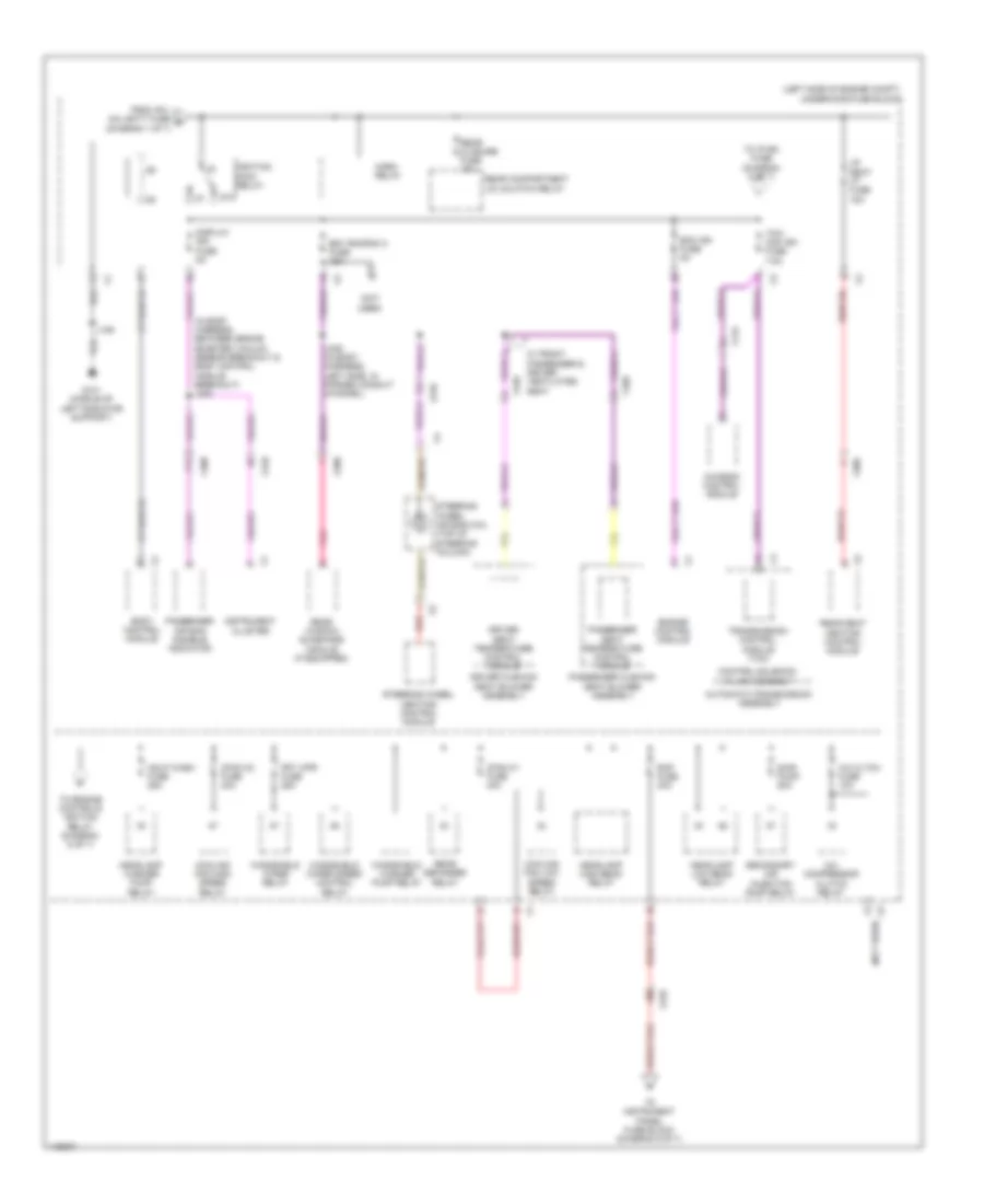
POWER DISTRIBUTION
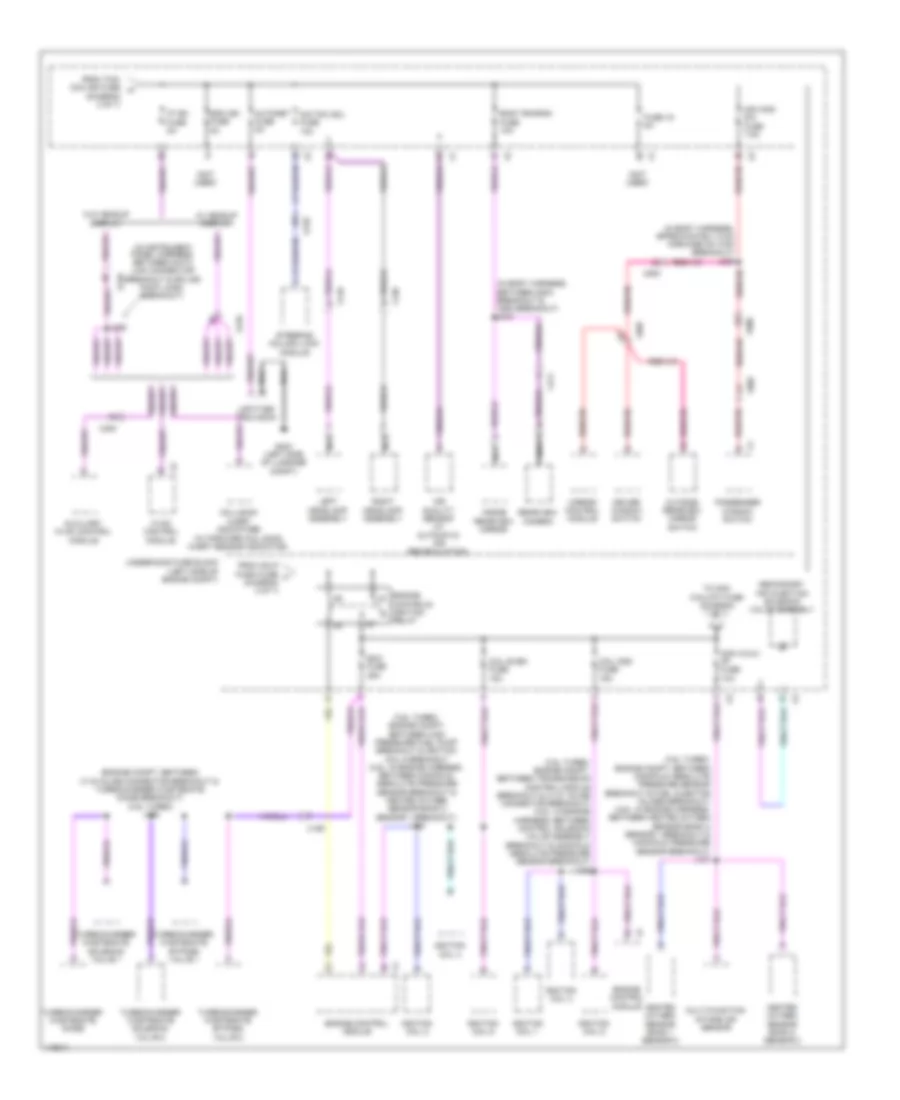
Power Distribution Wiring Diagram (1 of 7) for Cadillac XTS Livery 2014

List of elements for Power Distribution Wiring Diagram (1 of 7) for Cadillac XTS Livery 2014:
- (in sunroof harness) j398
- (left side of engine compt) underhood fuse block
- (not used)
- (passenger compt, between brake fluid level switch breakout & headlamp control module breakout) j207
- Abs pump fuse 60a
- Abs valve fuse 30a
- Afl/ahl batt fuse 5a
- Amp fuse 25a
- Audio amplifier
- Automatic transmission assembly
- Batt rvc fuse 5a
- Battery
- Battery fuse block (on battery)
- Bcm 6 fuse 15a
- Body control module
- Brake booster pump motor relay
- Brake system
- Brk vac pump fuse 25a
- Cann vnt fuse 5a
- Ccm fuse 20a
- Chassis control module
- Control solenoid valve assembly
- Driver seat memory control module
- Driver window motor
- Ecm batt fuse 5a
- Electronic brake control module
- Engine control module
- Eps fuse 30a
- Evaporative emission vent solenoid valve
- Front seat heating control module (if equipped)
- Fuse 1 60a
- Fuse 10a
- Fuse 2 60a
- Fuse 3 100a
- Fuse 30a
- Fuse 4 80a
- Fuse 5 250a
- Fuse 6 300a
- Generator
- Headlamp control module
- Heated seat rf fuse 15a
- Htd seat lf fuse 15a
- Keyless entry control module
- Left rear window motor
- Mem seat fuse 5a
- Parking brake control module
- Passenger seat memory control module
- Passenger window motor
- Peps batt fuse 5a
- Power steering control module
- Pwin frt fuse 30a
- Pwin rr fuse 30a
- Rear seat heating control module (if equipped)
- Red
- Right rear window motor
- Rr seat ht fuse 15a
- Starter motor
- Starter relay
- Str sol fuse 30a
- Sunroof control module (if equipped)
- Sunroof fuse 30a
- Sunroof sunshade motor module (if equipped)
- Tcm batt fuse 15a
- To ignition main relay (diagram 2 of 7)
- To instrument panel fuse block (diagram 3 of 7)
- To instrument panel fuse block (diagram 4 of 7)
- To rear body fuse block (diagram 4 of 7)
- To rear body fuse block (diagram 5 of 7)
- Transmission control module (tcm)
- Upa fuse 10a
- Ves
- W/ heavy duty
- W/o heavy duty
- X210
- X310
- X320
- X350
- X360
- X390
- X500
- X600
- X700
- X800
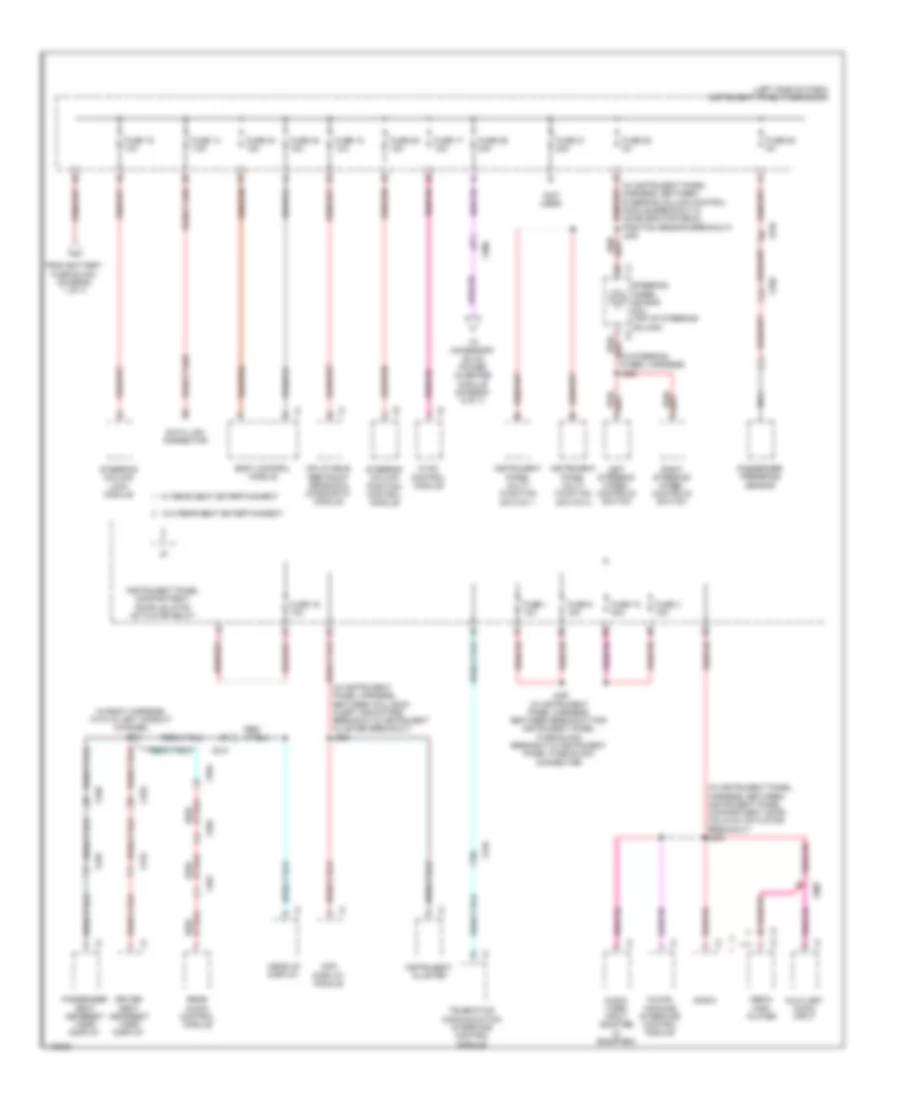
Power Distribution Wiring Diagram (2 of 7) for Cadillac XTS Livery 2014
List of elements for Power Distribution Wiring Diagram (2 of 7) for Cadillac XTS Livery 2014:
- (in body harness, between brake booster vacuum sensor breakout & body control module breakout) j208
- (left side of engine compt) underhood fuse block
- (not used)
- 87a
- A/c cltch fuse 10a
- A/c compressor clutch relay
- Automatic transmission assembly
- Bdy rncrnk 2 fuse 15a
- Body control module
- C12
- Cfan k1 fuse 40a
- Cfan k2 fuse 40a
- Chassis control module
- Control solenoid valve assembly
- Cooling fan high speed relay
- Cooling fan low speed relay
- Display ign fuse 5a
- Driver cushion seat blower assembly
- Driver seat temperature control module
- Ecm ign fuse 5a
- Engine control module
- From afl/ ahl batt fuse e (diagram 1 of 7)
- Frt wpr fuse 25a
- G101 (middle of left radiator support)
- Hdlp wash fuse 25a
- Headlamp high beam relay
- Headlamp low beam relay
- Headlamp washer pump relay
- Horn relay
- Ignition main relay
- Instrument cluster
- J109
- J336 (in body harness, left side, in formed conduit channel)
- Lr seat ht fuse 15a
- Passenger air bag disable indicator
- Passenger cushion seat blower assembly
- Passenger seat temperature control module
- Pnk
- Rap fuse 30a
- Rear closure fuse 10a
- Rear compartment lid unlatch relay
- Rear defogger relay
- Rear seat heating control module
- Rear window sunshade module (if equipped)
- Red
- Sair pump 50a
- Secondary air injection pump relay
- Steering wheel air bag coil (top of steering column)
- Steering wheel heating control module
- Tcm/ ccm ign fuse 7.5a
- To engine controls ignition relay (diagram 6 of 7)
- To instrument panel fuse block (diagram 5 of 7)
- To ip ign fuse (diagram 6 of 7)
- Transmission control module (tcm)
- W/ front passenger & driver ventilated seat
- Windshield washer pump relay
- Windshield wiper relay
- Windshield wiper speed control relay
- X115
- X210
- X310
- X320
- X360
- X398
- X400
Power Distribution Wiring Diagram (3 of 7) for Cadillac XTS Livery 2014
List of elements for Power Distribution Wiring Diagram (3 of 7) for Cadillac XTS Livery 2014:
- (in body harness, with in left conduit channel) j319
- (in instrument panel harness, between collision alert indicators breakout & instrument cluster breakout) j206
- (in instrument panel harness, between instrument panel compartment door unlatch actuator breakout) j235
- (in instrument panel harness, between steering column control module breakout & accelerator pedal position sensor breakout) j238
- (in steering wheel harness) j222
- (left side of dash) instrument panel fuse block
- (not used)
- Audio/ video input adapter (if equipped)
- Auxiliary audio input
- Body control module
- Data link connector
- Driver seat headrest video display
- From battery fuse block (diagram 1 of 7)
- Fuse 1 10a
- Fuse 14 7.5a
- Fuse 15 10a
- Fuse 16 10a
- Fuse 17 10a
- Fuse 18 30a
- Fuse 19 10a
- Fuse 20 5a
- Fuse 21 20a
- Fuse 22 2a
- Fuse 23 15a
- Fuse 24 15a
- Fuse 25 15a
- Fuse 26 30a
- Fuse 4 15a
- Fuse 5 15a
- Head-up display
- Human machine interface control module
- Hvac control module
- Inflatable restraint sensing & diagnostic module
- Info display module
- Instrument cluster
- Instrument panel compartment door unlatch actuator relay
- Instrument panel multi- function switch 1
- Instrument panel multi- function switch 2
- J229 (in instrument panel harness, between breakout for instrument panel fuse block breakout & instrument panel fuse block connector)
- Left steering wheel controls switch
- Media disc player
- Nca
- Passenger presence sensor
- Passenger seat headrest video display
- Radio
- Rear audio control module
- Right steering wheel controls switch
- Steering column lock module
- Steering column position control module
- Steering wheel air bag coil (top of steering column)
- Telematics communication interface control module
- To accessory dc/ac power inverter module (diagram 5 of 7)
- W/ rear seat entertainment
- W/o rear seat entertainment
- X210
- X300
- X310
- X315
- X320
- X325
- X355
- X361
- X362
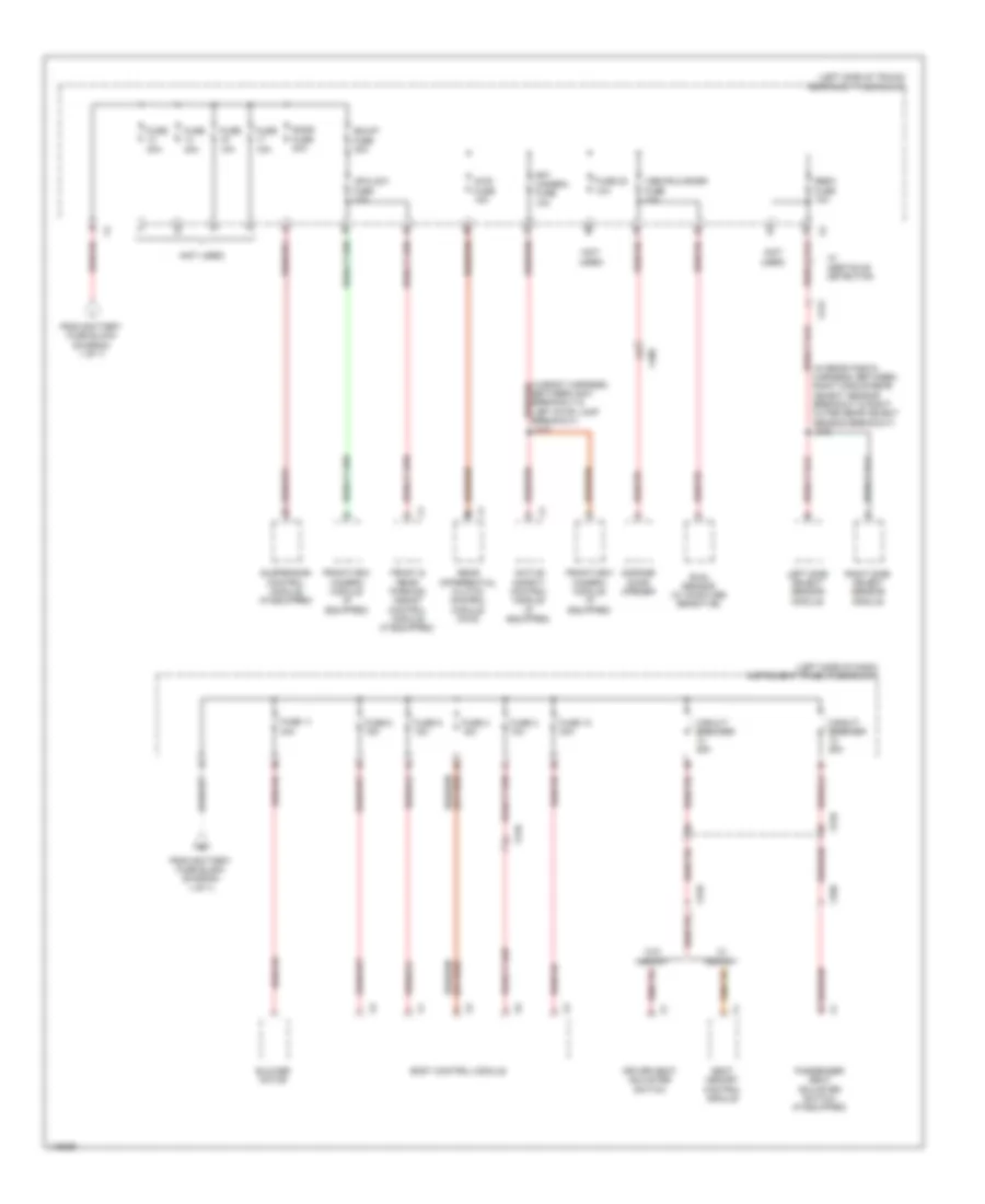
Power Distribution Wiring Diagram (4 of 7) for Cadillac XTS Livery 2014
List of elements for Power Distribution Wiring Diagram (4 of 7) for Cadillac XTS Livery 2014:
- (in rear fascia harness, between right middle rear object sensor breakout & right outer rear object sensor breakout) j478
- (left side of dash) instrument panel fuse block
- (left side of trunk) rear body fuse block
- (not used)
- Active safety control module (if equipped)
- Awd fuse 15a
- Blower motor
- Body control module
- Circuit breaker 25a
- Driver seat adjuster switch
- From battery fuse block (diagram 1 of 7)
- Front & rear parking assist control module (if equipped)
- Frontview camera module (if equipped)
- Frt camera fuse 10a
- Fuse 10 30a
- Fuse 10a
- Fuse 11 40a
- Fuse 15a
- Fuse 2 10a
- Fuse 22 10a
- Fuse 3 15a
- Fuse 30a
- Fuse 40a
- Fuse 8 15a
- Fuse 9 15a
- Garage door opener
- J410
- Left side object sensor module
- Passenger seat adjuster switch (if equipped)
- Rain sensor (w/ moisture sensitive)
- Rear differential clutch control module (awd)
- Right side object sensor module
- Sads fuse 30a
- Sbza fuse 10a
- Seat memory control module
- Shunt fuse 30a
- Suspension control module (if equipped)
- Ugdo/rlh/snsr fuse 10a
- Upa/ldw fuse 10a
- W/ memory
- W/ obstacle detection
- W/o memory
- X210
- X310
- X320
- X400
- X415
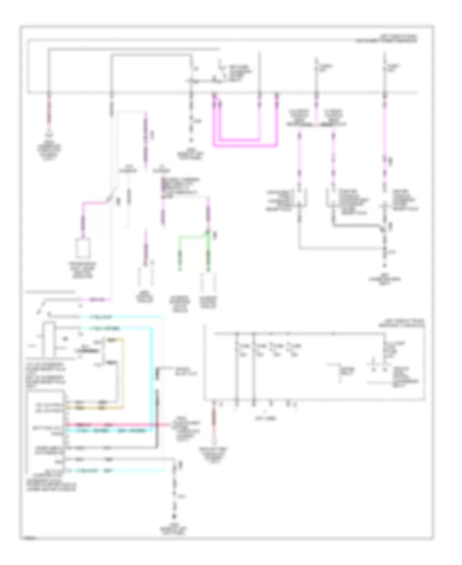
Power Distribution Wiring Diagram (5 of 7) for Cadillac XTS Livery 2014
List of elements for Power Distribution Wiring Diagram (5 of 7) for Cadillac XTS Livery 2014:
- (left side of dash) instrument panel fuse block
- (left side of trunk) rear body fuse block
- (not used)
- (or 6865)
- (or red)
- 110v
- 110v ac accessory power receptacle (110v) 220v ac accessory power receptacle (220v)
- 120 vac phs-a
- 220v
- 230 vac phs-a
- Accessory dc/ac power inverter module (under center console)
- Batt pos volt
- Body control module
- Center console accessory power receptacle
- Center console compartment accessory power receptacle
- Dc to ac inverter ctrl
- From battery fuse block (diagram 1 of 7)
- From instrument panel fuse block (diagram 3 of 7)
- From underhood fuse block (diagram 2 of 7)
- Fuse 25a
- Fuse 30a
- Fuse 6 20a
- Fuse 7 20a
- G305 (base of left kick panel)
- G307 (under driver's seat)
- Gnd
- Instrument panel accessory power receptacle
- J210
- J215
- J228
- Lvl comp mtr fuse 40a
- Modem serial data receive
- Nca
- Phs-b
- Retained accessory power relay
- Spare relay
- Sunroof
- Sunroof control module
- Sunroof sunshade motor module
- Transmission shift lever position indicator
- Vehicle level control compressor relay
- W/ front console rear receptacle
- W/o
- W/o front console rear receptacle
- X210
- X300
- X390
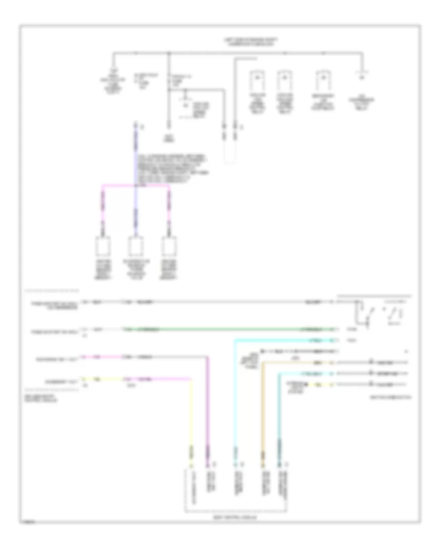
Power Distribution Wiring Diagram (6 of 7) for Cadillac XTS Livery 2014
List of elements for Power Distribution Wiring Diagram (6 of 7) for Cadillac XTS Livery 2014:
- (3.6l turbo: engine compt, between high pressure fuel pump breakout & ignition coil 6 breakout (3.6l: in engine harness, between manifold absolute pressure sensor breakout & heated oxygen sensor bank 2 sensor 1 breakout) j133
- (3.6l turbo: engine compt, between manifold absolute pressure sensor breakout & fuel injector inlines breakout) (3.6l: in engine harness, between heated oxygen sensor bank 2 sensor 1 breakout & manifold pressure sensor breakout) j107
- (3.6l turbo: engine compt, between transmission control module breakout & x115 inline connector breakout) (3.6l: in engine harness, between control solenoid valve assembly breakout & manifold absolute pressure sensor breakout) j106
- (diagram 2 of 7)
- (engine compt, between x115 inline connector breakout & turbocharger wastegate diode breakout) (3.6l turbo) j125
- (in body harness, approximately 5 cm forward of x700 breakout) j339
- (in body harness, between g203 breakout & x500 breakout) j218
- (in instrument panel harness, between data link connector breakout & splice pack jx200 breakout)
- (not used)
- Air quality sensor (w/ automatic air recirculation)
- Autonet fuse 5a
- Auxiliary hvac control module
- Body rncrnk fuse 10a
- Coil even fuse 15a
- Coil odd fuse 15a
- Collision alert indicators (w/ forward collision alert sensor indicator)
- Controls ignition relay
- Driver window switch
- Ecm fuse 25a
- Engine
- Engine control module
- From hdlp wash fuse f (diagram 2 of 7)
- From tcm/ ccm ign fuse h
- Fuse 19 5a
- G403 (left side of luggage compt)
- Heated oxygen sensor bank 1 sensor 2
- Heated oxygen sensor bank 2 sensor 2
- Hvac control module
- Ignition coil 1
- Ignition coil 2
- Ignition coil 3
- Ignition coil 4
- Ignition coil 5
- Ignition coil 6
- Inside rearview mirror
- Ip ign fuse 5a
- J226
- Left headlamp assembly
- Mir wnd sw fuse 7.5a
- Mirror control module
- Multi-function intake air sensor
- Nca
- Non walk pf fuse 10a
- Not r/c sol fuse 10a
- Outside rearview mirror switch
- Passenger window switch
- Rearview camera
- Right headlamp assembly
- Sdm ign fuse 5a
- Secondary air injection solenoid valve assembly
- Steering column lock module
- To non walk pt fuse (diagram 7 of 7)
- Turbocharger wastegate bypass valve 1
- Turbocharger wastegate bypass valve 2
- Turbocharger wastegate diode
- Turbocharger wastegate solenoid valve 1
- Turbocharger wastegate solenoid valve 2
- Underhood fuse block (left side of engine compt)
- Upfitter provision
- W/ headup display
- W/o headup display
- X110
- X120
- X159
- X210
- X300
- X411
- X500
- X505
- X600
- X605
Power Distribution Wiring Diagram (7 of 7) for Cadillac XTS Livery 2014
List of elements for Power Distribution Wiring Diagram (7 of 7) for Cadillac XTS Livery 2014:
- (3.6l: in engine harness, between control solenoid valve assembly breakout & manifold absolute pressure sensor breakout) (3.6l turbo: engine compt, between ignition coil 2 breakout & ignition coil 4 breakout) j108
- (left side of engine compt) underhood fuse block
- (not used)
- A/c compressor clutch relay
- Acc ind
- Acc led sig ign mode sw
- Accessory volt
- Body control module
- Cooling fan high speed control relay
- Cooling fan low speed relay
- Cooling fan speed control relay
- Evaporative emission purge solenoid valve
- Fan rly a fuse 10a
- From non walk pf fuse (diagram 6 of 7)
- G203 (base of left kick panel)
- Heated oxygen sensor bank 1 sensor 1
- Heated oxygen sensor bank 2 sensor 1
- Ign 1 volt run/crank
- Ignition mode switch
- Illu ind
- Interior lights system
- J203
- Keyless entry control module
- Mode volt ign mode sw
- Nca
- Non walk pt fuse 10a
- Passive start sw sig 2
- Passive start sw sig 2 low reference
- Run/crank ign 1 volt
- Secondary air injection pump relay
- Start ind
- Start led sig ign mode sw
- X210