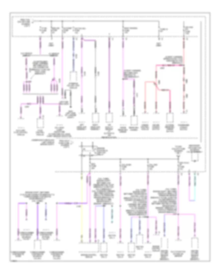
POWER DISTRIBUTION
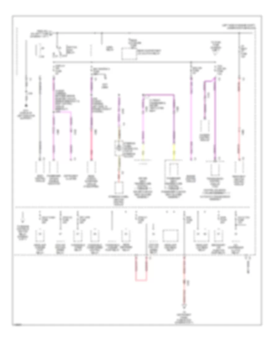
Power Distribution Wiring Diagram (1 of 7) for Cadillac XTS Vsport Premium 2014

List of elements for Power Distribution Wiring Diagram (1 of 7) for Cadillac XTS Vsport Premium 2014:
- (in sunroof harness) j398
- (left side of engine compt) underhood fuse block
- (not used)
- (passenger compt, between brake fluid level switch breakout & headlamp control module breakout) j207
- Abs pump fuse 60a
- Abs valve fuse 30a
- Afl/ahl batt fuse 5a
- Amp fuse 25a
- Audio amplifier
- Automatic transmission assembly
- Batt rvc fuse 5a
- Battery
- Battery fuse block (on battery)
- Bcm 6 fuse 15a
- Body control module
- Brake booster pump motor relay
- Brake system
- Brk vac pump fuse 25a
- Cann vnt fuse 5a
- Ccm fuse 20a
- Chassis control module
- Control solenoid valve assembly
- Driver seat memory control module
- Driver window motor
- Ecm batt fuse 5a
- Electronic brake control module
- Engine control module
- Eps fuse 30a
- Evaporative emission vent solenoid valve
- Front seat heating control module (if equipped)
- Fuse 1 60a
- Fuse 10a
- Fuse 2 60a
- Fuse 3 100a
- Fuse 30a
- Fuse 4 80a
- Fuse 5 250a
- Fuse 6 300a
- Generator
- Headlamp control module
- Heated seat rf fuse 15a
- Htd seat lf fuse 15a
- Keyless entry control module
- Left rear window motor
- Mem seat fuse 5a
- Parking brake control module
- Passenger seat memory control module
- Passenger window motor
- Peps batt fuse 5a
- Power steering control module
- Pwin frt fuse 30a
- Pwin rr fuse 30a
- Rear seat heating control module (if equipped)
- Red
- Right rear window motor
- Rr seat ht fuse 15a
- Starter motor
- Starter relay
- Str sol fuse 30a
- Sunroof control module (if equipped)
- Sunroof fuse 30a
- Sunroof sunshade motor module (if equipped)
- Tcm batt fuse 15a
- To ignition main relay (diagram 2 of 7)
- To instrument panel fuse block (diagram 3 of 7)
- To instrument panel fuse block (diagram 4 of 7)
- To rear body fuse block (diagram 4 of 7)
- To rear body fuse block (diagram 5 of 7)
- Transmission control module (tcm)
- Upa fuse 10a
- Ves
- W/ heavy duty
- W/o heavy duty
- X210
- X310
- X320
- X350
- X360
- X390
- X500
- X600
- X700
- X800
Power Distribution Wiring Diagram (2 of 7) for Cadillac XTS Vsport Premium 2014
List of elements for Power Distribution Wiring Diagram (2 of 7) for Cadillac XTS Vsport Premium 2014:
- (in body harness, between brake booster vacuum sensor breakout & body control module breakout) j208
- (left side of engine compt) underhood fuse block
- (not used)
- 87a
- A/c cltch fuse 10a
- A/c compressor clutch relay
- Automatic transmission assembly
- Bdy rncrnk 2 fuse 15a
- Body control module
- C12
- Cfan k1 fuse 40a
- Cfan k2 fuse 40a
- Chassis control module
- Control solenoid valve assembly
- Cooling fan high speed relay
- Cooling fan low speed relay
- Display ign fuse 5a
- Driver cushion seat blower assembly
- Driver seat temperature control module
- Ecm ign fuse 5a
- Engine control module
- From afl/ ahl batt fuse e (diagram 1 of 7)
- Frt wpr fuse 25a
- G101 (middle of left radiator support)
- Hdlp wash fuse 25a
- Headlamp high beam relay
- Headlamp low beam relay
- Headlamp washer pump relay
- Horn relay
- Ignition main relay
- Instrument cluster
- J109
- J336 (in body harness, left side, in formed conduit channel)
- Lr seat ht fuse 15a
- Passenger air bag disable indicator
- Passenger cushion seat blower assembly
- Passenger seat temperature control module
- Pnk
- Rap fuse 30a
- Rear closure fuse 10a
- Rear compartment lid unlatch relay
- Rear defogger relay
- Rear seat heating control module
- Rear window sunshade module (if equipped)
- Red
- Sair pump 50a
- Secondary air injection pump relay
- Steering wheel air bag coil (top of steering column)
- Steering wheel heating control module
- Tcm/ ccm ign fuse 7.5a
- To engine controls ignition relay (diagram 6 of 7)
- To instrument panel fuse block (diagram 5 of 7)
- To ip ign fuse (diagram 6 of 7)
- Transmission control module (tcm)
- W/ front passenger & driver ventilated seat
- Windshield washer pump relay
- Windshield wiper relay
- Windshield wiper speed control relay
- X115
- X210
- X310
- X320
- X360
- X398
- X400
Power Distribution Wiring Diagram (3 of 7) for Cadillac XTS Vsport Premium 2014
List of elements for Power Distribution Wiring Diagram (3 of 7) for Cadillac XTS Vsport Premium 2014:
- (in body harness, with in left conduit channel) j319
- (in instrument panel harness, between collision alert indicators breakout & instrument cluster breakout) j206
- (in instrument panel harness, between instrument panel compartment door unlatch actuator breakout) j235
- (in instrument panel harness, between steering column control module breakout & accelerator pedal position sensor breakout) j238
- (in steering wheel harness) j222
- (left side of dash) instrument panel fuse block
- (not used)
- Audio/ video input adapter (if equipped)
- Auxiliary audio input
- Body control module
- Data link connector
- Driver seat headrest video display
- From battery fuse block (diagram 1 of 7)
- Fuse 1 10a
- Fuse 14 7.5a
- Fuse 15 10a
- Fuse 16 10a
- Fuse 17 10a
- Fuse 18 30a
- Fuse 19 10a
- Fuse 20 5a
- Fuse 21 20a
- Fuse 22 2a
- Fuse 23 15a
- Fuse 24 15a
- Fuse 25 15a
- Fuse 26 30a
- Fuse 4 15a
- Fuse 5 15a
- Head-up display
- Human machine interface control module
- Hvac control module
- Inflatable restraint sensing & diagnostic module
- Info display module
- Instrument cluster
- Instrument panel compartment door unlatch actuator relay
- Instrument panel multi- function switch 1
- Instrument panel multi- function switch 2
- J229 (in instrument panel harness, between breakout for instrument panel fuse block breakout & instrument panel fuse block connector)
- Left steering wheel controls switch
- Media disc player
- Nca
- Passenger presence sensor
- Passenger seat headrest video display
- Radio
- Rear audio control module
- Right steering wheel controls switch
- Steering column lock module
- Steering column position control module
- Steering wheel air bag coil (top of steering column)
- Telematics communication interface control module
- To accessory dc/ac power inverter module (diagram 5 of 7)
- W/ rear seat entertainment
- W/o rear seat entertainment
- X210
- X300
- X310
- X315
- X320
- X325
- X355
- X361
- X362
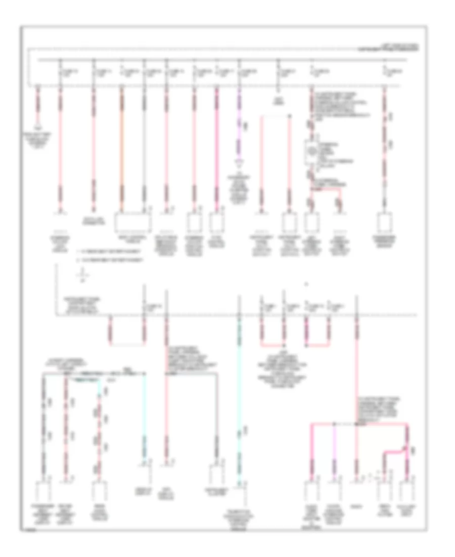
Power Distribution Wiring Diagram (4 of 7) for Cadillac XTS Vsport Premium 2014
List of elements for Power Distribution Wiring Diagram (4 of 7) for Cadillac XTS Vsport Premium 2014:
- (in rear fascia harness, between right middle rear object sensor breakout & right outer rear object sensor breakout) j478
- (left side of dash) instrument panel fuse block
- (left side of trunk) rear body fuse block
- (not used)
- Active safety control module (if equipped)
- Awd fuse 15a
- Blower motor
- Body control module
- Circuit breaker 25a
- Driver seat adjuster switch
- From battery fuse block (diagram 1 of 7)
- Front & rear parking assist control module (if equipped)
- Frontview camera module (if equipped)
- Frt camera fuse 10a
- Fuse 10 30a
- Fuse 10a
- Fuse 11 40a
- Fuse 15a
- Fuse 2 10a
- Fuse 22 10a
- Fuse 3 15a
- Fuse 30a
- Fuse 40a
- Fuse 8 15a
- Fuse 9 15a
- Garage door opener
- J410
- Left side object sensor module
- Passenger seat adjuster switch (if equipped)
- Rain sensor (w/ moisture sensitive)
- Rear differential clutch control module (awd)
- Right side object sensor module
- Sads fuse 30a
- Sbza fuse 10a
- Seat memory control module
- Shunt fuse 30a
- Suspension control module (if equipped)
- Ugdo/rlh/snsr fuse 10a
- Upa/ldw fuse 10a
- W/ memory
- W/ obstacle detection
- W/o memory
- X210
- X310
- X320
- X400
- X415
Power Distribution Wiring Diagram (5 of 7) for Cadillac XTS Vsport Premium 2014
List of elements for Power Distribution Wiring Diagram (5 of 7) for Cadillac XTS Vsport Premium 2014:
- (left side of dash) instrument panel fuse block
- (left side of trunk) rear body fuse block
- (not used)
- (or 6865)
- (or red)
- 110v
- 110v ac accessory power receptacle (110v) 220v ac accessory power receptacle (220v)
- 120 vac phs-a
- 220v
- 230 vac phs-a
- Accessory dc/ac power inverter module (under center console)
- Batt pos volt
- Body control module
- Center console accessory power receptacle
- Center console compartment accessory power receptacle
- Dc to ac inverter ctrl
- From battery fuse block (diagram 1 of 7)
- From instrument panel fuse block (diagram 3 of 7)
- From underhood fuse block (diagram 2 of 7)
- Fuse 25a
- Fuse 30a
- Fuse 6 20a
- Fuse 7 20a
- G305 (base of left kick panel)
- G307 (under driver's seat)
- Gnd
- Instrument panel accessory power receptacle
- J210
- J215
- J228
- Lvl comp mtr fuse 40a
- Modem serial data receive
- Nca
- Phs-b
- Retained accessory power relay
- Spare relay
- Sunroof
- Sunroof control module
- Sunroof sunshade motor module
- Transmission shift lever position indicator
- Vehicle level control compressor relay
- W/ front console rear receptacle
- W/o
- W/o front console rear receptacle
- X210
- X300
- X390
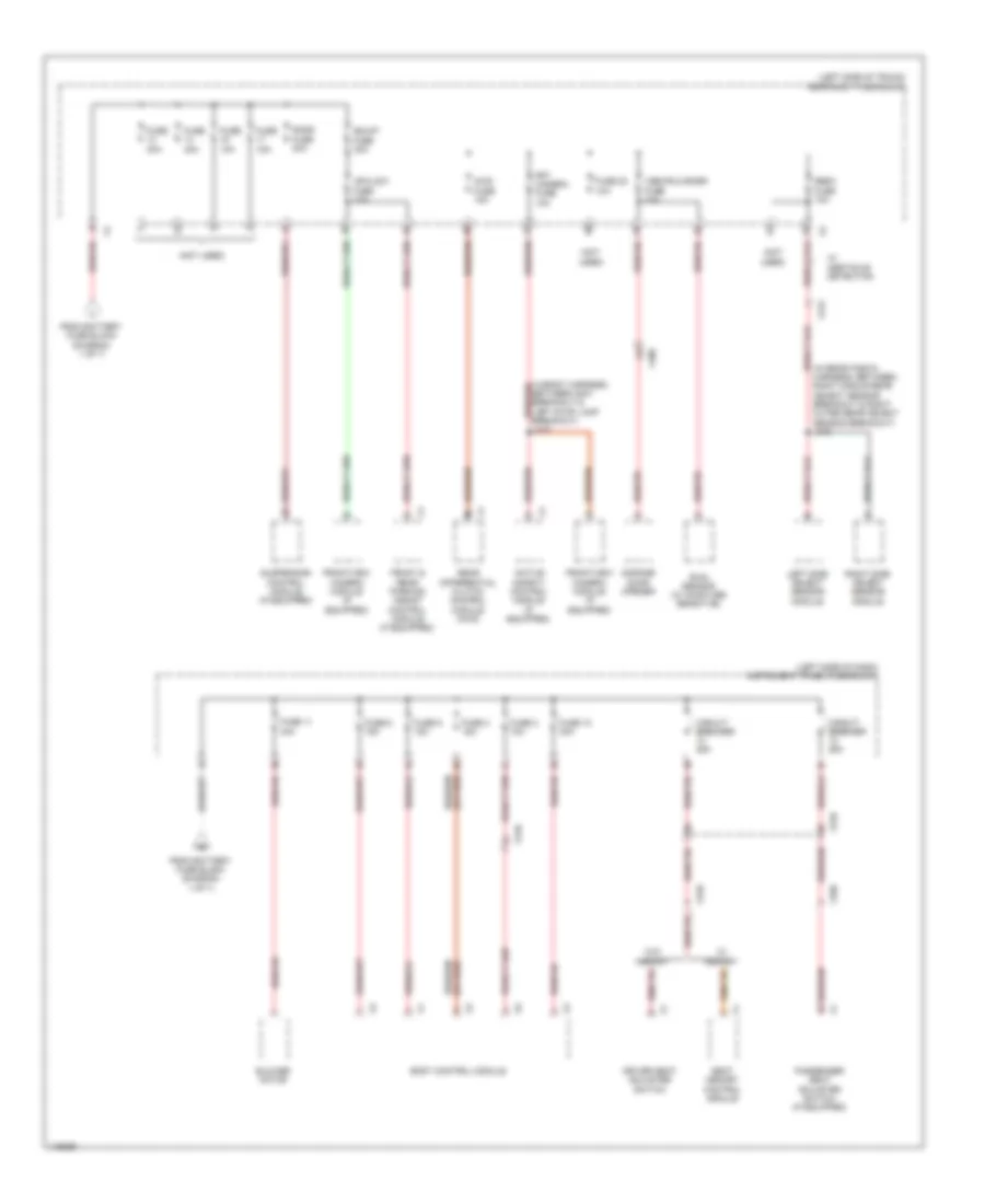
Power Distribution Wiring Diagram (6 of 7) for Cadillac XTS Vsport Premium 2014
List of elements for Power Distribution Wiring Diagram (6 of 7) for Cadillac XTS Vsport Premium 2014:
- (3.6l turbo: engine compt, between high pressure fuel pump breakout & ignition coil 6 breakout (3.6l: in engine harness, between manifold absolute pressure sensor breakout & heated oxygen sensor bank 2 sensor 1 breakout) j133
- (3.6l turbo: engine compt, between manifold absolute pressure sensor breakout & fuel injector inlines breakout) (3.6l: in engine harness, between heated oxygen sensor bank 2 sensor 1 breakout & manifold pressure sensor breakout) j107
- (3.6l turbo: engine compt, between transmission control module breakout & x115 inline connector breakout) (3.6l: in engine harness, between control solenoid valve assembly breakout & manifold absolute pressure sensor breakout) j106
- (diagram 2 of 7)
- (engine compt, between x115 inline connector breakout & turbocharger wastegate diode breakout) (3.6l turbo) j125
- (in body harness, approximately 5 cm forward of x700 breakout) j339
- (in body harness, between g203 breakout & x500 breakout) j218
- (in instrument panel harness, between data link connector breakout & splice pack jx200 breakout)
- (not used)
- Air quality sensor (w/ automatic air recirculation)
- Autonet fuse 5a
- Auxiliary hvac control module
- Body rncrnk fuse 10a
- Coil even fuse 15a
- Coil odd fuse 15a
- Collision alert indicators (w/ forward collision alert sensor indicator)
- Controls ignition relay
- Driver window switch
- Ecm fuse 25a
- Engine
- Engine control module
- From hdlp wash fuse f (diagram 2 of 7)
- From tcm/ ccm ign fuse h
- Fuse 19 5a
- G403 (left side of luggage compt)
- Heated oxygen sensor bank 1 sensor 2
- Heated oxygen sensor bank 2 sensor 2
- Hvac control module
- Ignition coil 1
- Ignition coil 2
- Ignition coil 3
- Ignition coil 4
- Ignition coil 5
- Ignition coil 6
- Inside rearview mirror
- Ip ign fuse 5a
- J226
- Left headlamp assembly
- Mir wnd sw fuse 7.5a
- Mirror control module
- Multi-function intake air sensor
- Nca
- Non walk pf fuse 10a
- Not r/c sol fuse 10a
- Outside rearview mirror switch
- Passenger window switch
- Rearview camera
- Right headlamp assembly
- Sdm ign fuse 5a
- Secondary air injection solenoid valve assembly
- Steering column lock module
- To non walk pt fuse (diagram 7 of 7)
- Turbocharger wastegate bypass valve 1
- Turbocharger wastegate bypass valve 2
- Turbocharger wastegate diode
- Turbocharger wastegate solenoid valve 1
- Turbocharger wastegate solenoid valve 2
- Underhood fuse block (left side of engine compt)
- Upfitter provision
- W/ headup display
- W/o headup display
- X110
- X120
- X159
- X210
- X300
- X411
- X500
- X505
- X600
- X605
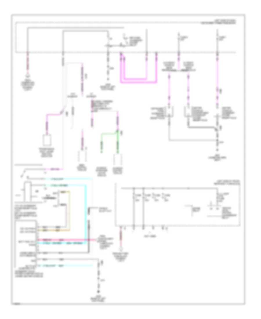
Power Distribution Wiring Diagram (7 of 7) for Cadillac XTS Vsport Premium 2014
List of elements for Power Distribution Wiring Diagram (7 of 7) for Cadillac XTS Vsport Premium 2014:
- (3.6l: in engine harness, between control solenoid valve assembly breakout & manifold absolute pressure sensor breakout) (3.6l turbo: engine compt, between ignition coil 2 breakout & ignition coil 4 breakout) j108
- (left side of engine compt) underhood fuse block
- (not used)
- A/c compressor clutch relay
- Acc ind
- Acc led sig ign mode sw
- Accessory volt
- Body control module
- Cooling fan high speed control relay
- Cooling fan low speed relay
- Cooling fan speed control relay
- Evaporative emission purge solenoid valve
- Fan rly a fuse 10a
- From non walk pf fuse (diagram 6 of 7)
- G203 (base of left kick panel)
- Heated oxygen sensor bank 1 sensor 1
- Heated oxygen sensor bank 2 sensor 1
- Ign 1 volt run/crank
- Ignition mode switch
- Illu ind
- Interior lights system
- J203
- Keyless entry control module
- Mode volt ign mode sw
- Nca
- Non walk pt fuse 10a
- Passive start sw sig 2
- Passive start sw sig 2 low reference
- Run/crank ign 1 volt
- Secondary air injection pump relay
- Start ind
- Start led sig ign mode sw
- X210