ANTI-LOCK BRAKES
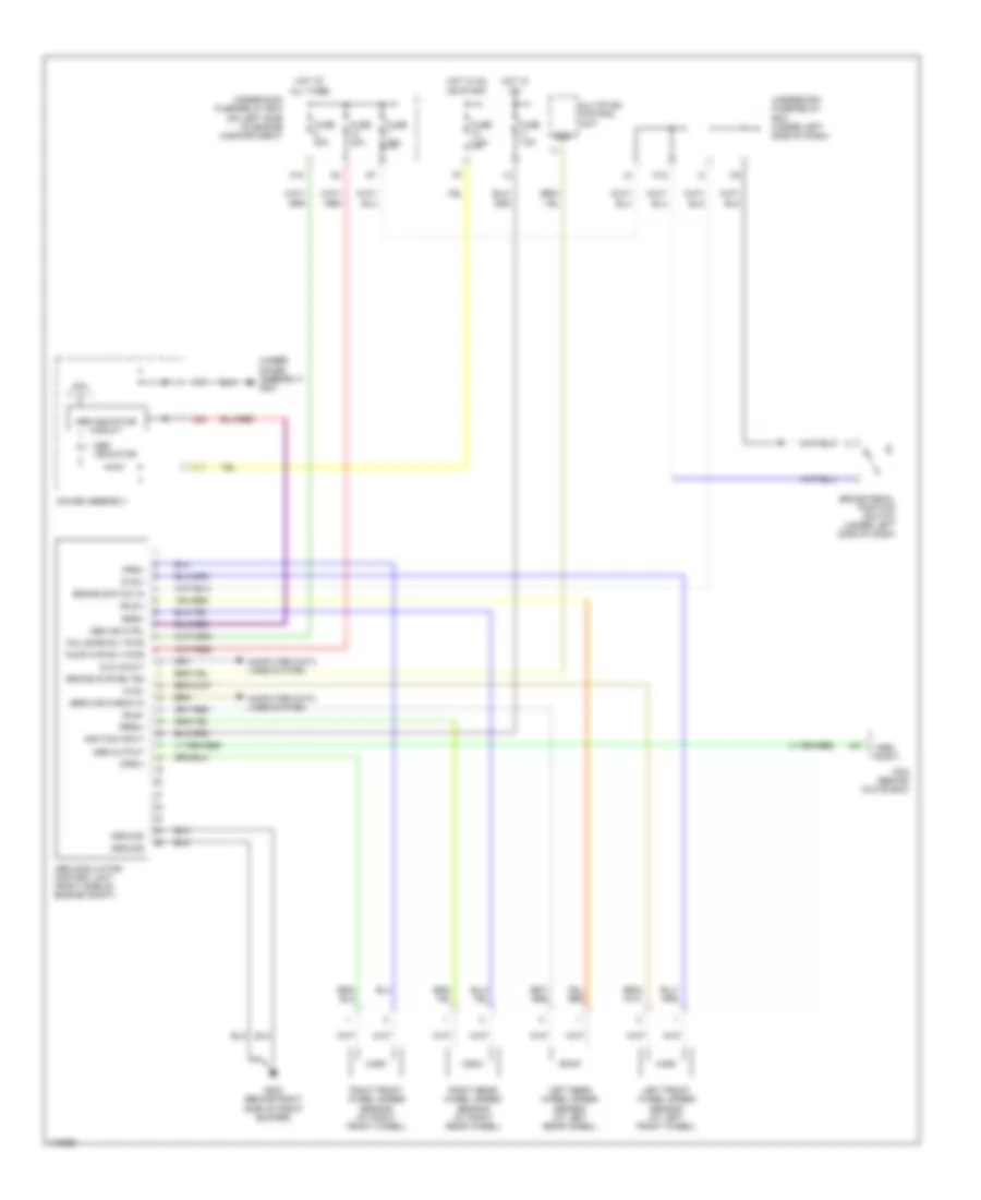
Anti-lock Brakes Wiring Diagram, Except Hatchback & Hybrid for Honda Civic LX 2003

List of elements for Anti-lock Brakes Wiring Diagram, Except Hatchback & Hybrid for Honda Civic LX 2003:
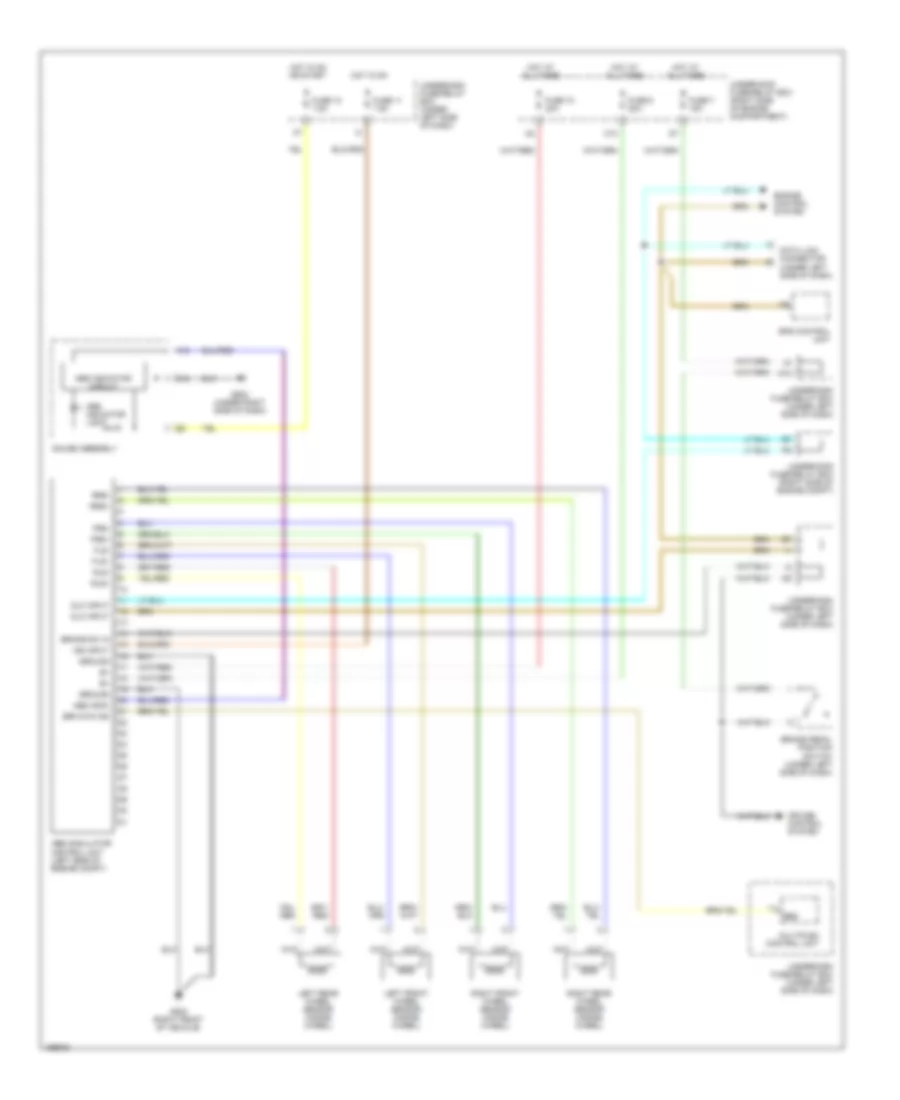
Anti-lock Brakes Wiring Diagram, Hatchback for Honda Civic LX 2003
List of elements for Anti-lock Brakes Wiring Diagram, Hatchback for Honda Civic LX 2003:
Anti-lock Brakes Wiring Diagram, Hybrid for Honda Civic LX 2003
List of elements for Anti-lock Brakes Wiring Diagram, Hybrid for Honda Civic LX 2003: