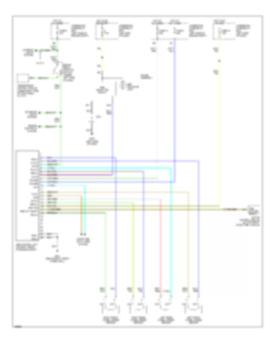
ANTI-LOCK BRAKES
Anti-lock Brakes Wiring Diagram for Honda Insight 2004
List of elements for Anti-lock Brakes Wiring Diagram for Honda Insight 2004:
- 7.5a
- A14
- Abs control unit (on right front of engine compt)
- Abs indicator circuit
- Abs indicator light
- Abs out (busy)
- Abs system (busy)
- B12
- B15
- B17
- Brake pedal position switch (under left side of dash)
- C571
- Computer data lines system
- Dlc
- Engine controls system
- Exterior lights system
- Flw(+)
- Flw(-)
- Frw(+)
- Frw(-)
- Fuse 14 20a
- Fuse 16 7.5a
- Fuse 3 30a
- Fuse 6 10a
- G201 (above right front wheelwell)
- G402 (left side of dash)
- Gauge assembly
- Gnd 1
- Gnd 2
- Hot at all times
- Hot in on or acc
- Hot in on or start
- Ignition
- Interior lights system
- Left front wheel speed sensor
- Left rear wheel speed sensor
- Motor control module (on top front of battery module
- Power
- Right front wheel speed sensor
- Right rear wheel speed sensor
- Rlw(+)
- Rlw(-)
- Rrw(+)
- Rrw(-)
- Scs
- Stop
- Transmission control module (under right side of kick panel) (w/ cvt)
- Underdash fuse/relay box (left end of dash)
- Underdash fuse/relay box (left side of dash)
- Underhood fuse/relay box (left side of engine compt)
- W/ cvt
- Walp
 English