ANTI-LOCK BRAKES
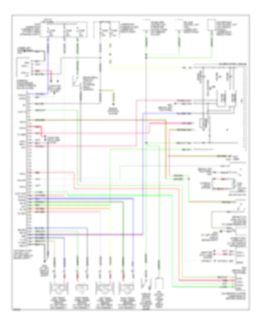
Anti-lock Brakes Wiring Diagram for Honda S2000 2008
List of elements for Anti-lock Brakes Wiring Diagram for Honda S2000 2008:
- (behind left kick panel) g501
- (not used) c404
- (under left side of dash) g401
- A12
- A18
- Abs
- Abs ind
- Act
- B11
- B14
- B20
- B23
- B24
- B25
- Bfls
- Bksw
- Brake fluid level switch (on master cylinder reservoir)
- Brake pedal position switch (on brake pedal support)
- Brake system ind
- Can-h
- Can-l
- Can1 h
- Can1 l
- Circuit abs ind
- Clst gnd
- Clst ig
- Computer data lines system
- Convertible top control unit (usa: base & canada) (under right side of dash)
- Cpu
- Diag-k
- Drive circuit
- Drl control unit (under left side of dash)
- Drl sub control unit (usa) (under left side of dash)
- E11
- E22
- E24
- Ecm (behind left kick panel)
- Engine controls system
- Fl +b
- Fl-gnd
- Fr +b
- Fr-gnd
- Fuse 15a
- Fuse 30a
- Fuse 7.5a
- G301 (at left front side of engine compt)
- G303 (at left rear of engine compt)
- G501 (behind left kick panel)
- Gauge control module
- Gnd
- Gnd p
- Gnd v
- Hot at all times
- Hot in on
- Ig1
- Immobilizer control unit & receiver (on right side of steering column)
- Ind vsa ctivation
- Interior lights system
- Intermittent wiper relay (at left rear of engine compt)
- Left front wheel speed sensor (at left front hub assembly)
- Left rear wheel speed sensor (at left rear hub assembly)
- Main under-hood fuse/relay box (at right rear of engine compt)
- Parking brake switch (at base of parking brake lever)
- Pnk
- Pwr
- Pwr in
- Red
- Right front wheel speed sensor (at right front hub assembly)
- Right rear wheel speed sensor (at right rear hub assembly)
- Rl +b
- Rl-gnd
- Rr +b
- Rr-gnd
- Steering angle sensor (under steering column cover)
- Under-dash fuse/relay box (under left side of dash)
- Vsa ind
- Vsa ind circuit
- Vsa modulator control unit (at left rear of engine compt)
- Vsa off
- Vsa off switch
- Vsa off switch light
- Vsa sensor cluster (under rear of center console)
- Wl ebd
 English