ENGINE PERFORMANCE
2.4L
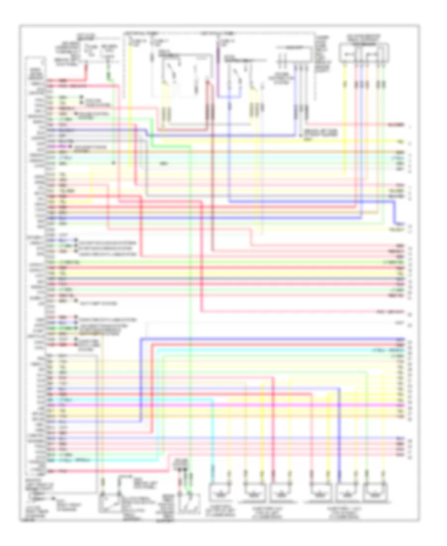
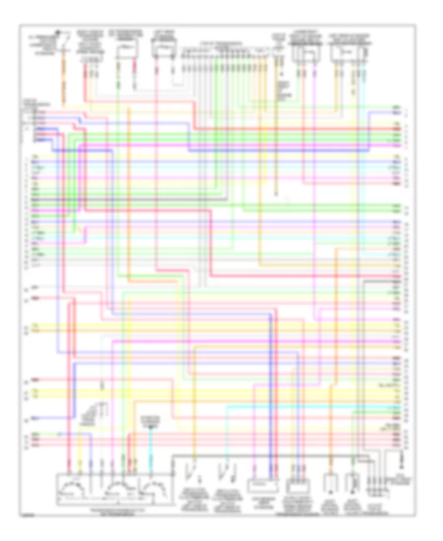
2.4L, Engine Performance Wiring Diagram (1 of 5) for Honda Accord EX 2010

List of elements for 2.4L, Engine Performance Wiring Diagram (1 of 5) for Honda Accord EX 2010:
- (left side of engine) g101
- (thermal joint) s1
- A10
- A11
- A12
- A13
- A14
- A15
- A16
- A17
- A18
- A19
- A20
- A21
- A22
- A23
- A24
- A25
- A26
- A27
- A28
- A29
- A30
- A31
- A32
- A33
- A34
- A35
- A36
- A37
- A38
- A39
- A40
- A41
- A42
- A43
- A44
- A45
- A46
- A47
- A48
- A49
- Acc
- Acpd
- Air conditioning system
- App sensor (on accelerator pedal support)
- Apsa
- Apsb
- Atp2-1
- Atpd3
- Atpn
- Atpp
- Atpr
- B10
- B11
- B12
- B13
- B14
- B15
- B16
- B17
- B18
- B19
- B20
- B21
- Barometer sensor
- Bksw
- Bkswnc
- Can h
- Can l
- Computer data lines system
- Cooling fans system
- Crmtcls
- Cruise control system
- Driver's under-dash fuse/relay box (behind left kick panel)
- Ecm/pcm (left front of engine compt)
- Ect2
- Eld
- Eld unit
- Etcs control relay
- Etcsrly
- F12
- Fanc
- Ftp
- Fuse 10a
- Fuse 17 15a
- Fuse 18 15a
- G101 (left side of engine)
- G301 (behind left side of front bumper)
- Hot at all times
- Hot in on or start
- Igp
- Imofpr
- J/c c101 (left side of engine compt)
- Mrly
- Navigation & sound systems
- Nep
- Oil pressure switch (at right front of engine)
- Op2sw
- Op3sw
- Opsw
- Pcs
- Pg 1
- Pg 2
- Pgm fi main relay
- Pnk
- Power distribution system
- Pspsw
- Red
- S net
- S1 (thermal joint)
- Scs
- Sg 4
- Sg 5
- Sg6
- Sha
- Shb
- Shc
- Shift control solenoid valve a
- Shift control solenoid valve b
- Shift control solenoid valve c
- Sls
- So2shtc
- Sound systems
- Starting/ charging system
- Starting/charging system
- Subrly
- Transmission range switch (on rear of transmission)
- Under- hood fuse/ relay box (left rear of engine compt)
- Vbsol
- Vcc 4
- Vcc 5
- Vcc2
- Vcc6
- Vssout
- Vsv
- Wen
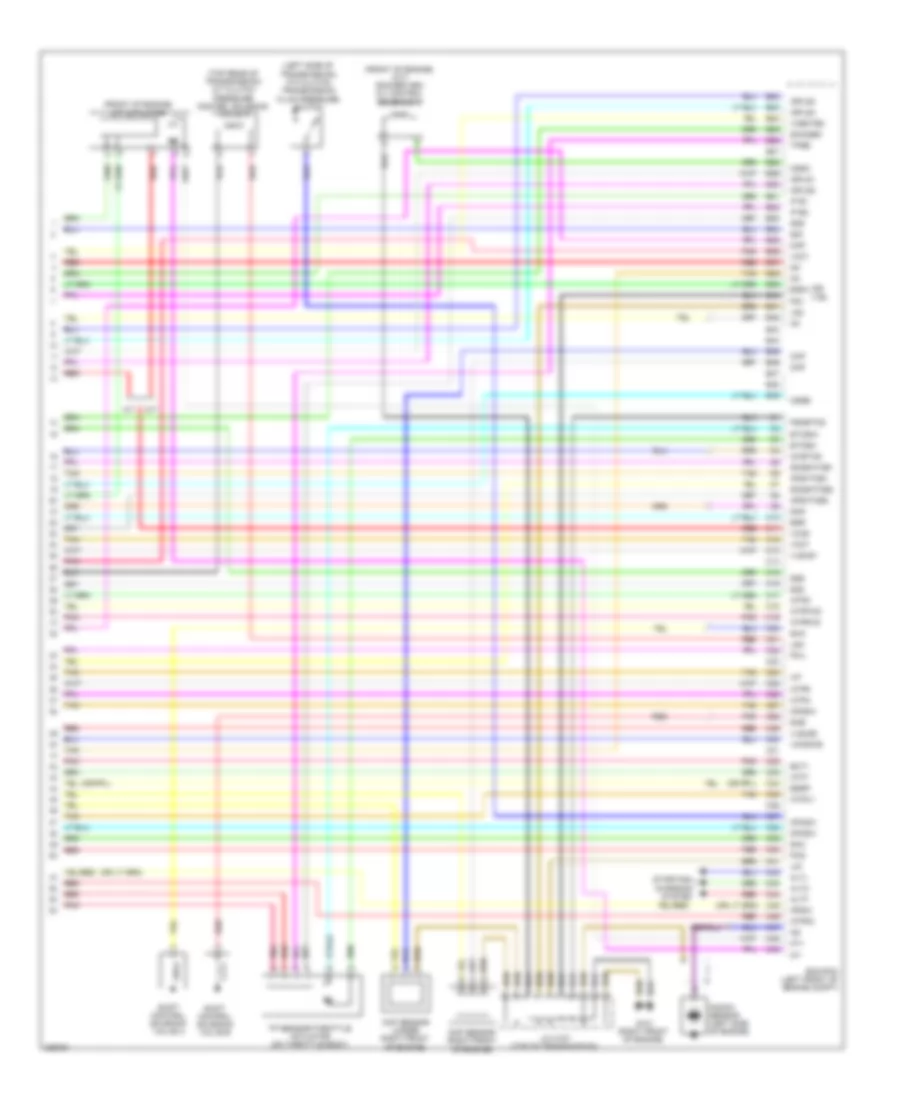
2.4L, Engine Performance Wiring Diagram (2 of 5) for Honda Accord EX 2010
List of elements for 2.4L, Engine Performance Wiring Diagram (2 of 5) for Honda Accord EX 2010:
- (left side of engine compt) j/c c101
- (lower left front of engine compt) ect sensor 2
- (right rear of engine compt) psp switch
- (right side of engine compt) a/c pressure sensor
- (under middle rear of vehicle) ftp sensor
- (under middle rear of vehicle, on evap control canister) evap canister vent shut valve
- 2nd clutch transmission fluid pressure switch a (left side of transmission)
- 3rd clutch transmission fluid pressure switch b (on side of transmission)
- A14
- A15
- A17
- B10
- B22
- Brake pedal position switch (on brake pedal support)
- Cruise control system
- D10
- Driver's under-dash fuse/relay box (behind left kick panel)
- Evap canister purge valve (rear of engine)
- F14
- F22
- F31
- Fuel gauge sending unit
- Fuel pump
- Fuel pump relay
- Fuel tank unit (top of fuel tank)
- Fuse 7 15a
- Fuse 9 20a
- G201 (behind right side of dash)
- G603 (left rear of floor)
- Hot in on or start
- Instrument cluster system
- J/c c103 (rear of engine)
- Pnk
- Red
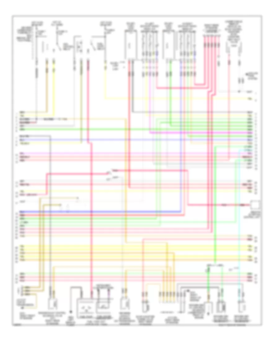
2.4L, Engine Performance Wiring Diagram (3 of 5) for Honda Accord EX 2010
List of elements for 2.4L, Engine Performance Wiring Diagram (3 of 5) for Honda Accord EX 2010:
- 10v stabilizer circuit
- 5v stabilizer circuit/controller area network controller
- A/c condenser fan relay
- A/c diode b
- A/t gear position dimming circuit
- A/t gear position indicator drive circuit
- A16
- B23
- Ckp sensor (under right front of engine)
- Cmp sensor b (rear of engine)
- Compulsory turning off circuit
- Compulsory turning on circuit
- Computer data lines system
- Fall safe circuit
- Fast controller area network transceiver
- Fuse 13 15a
- Fuse 14 15a
- Fuse 15 10a
- Fuse 21 7.5a
- G101 (left side of engine)
- Gauge control module
- Hot at all times
- Iat
- Ignition coil relay
- Injectors (top of engine)
- J/c c101 (left side of engine compt)
- Maf
- Maf/iat sensor (on intake air duct)
- Mil ind
- Pgm fi sub relay
- Pnk
- Red
- S3 (thermal joint)
- Under- hood fuse/ relay box (left rear of engine compt)
- Warning drive circuit
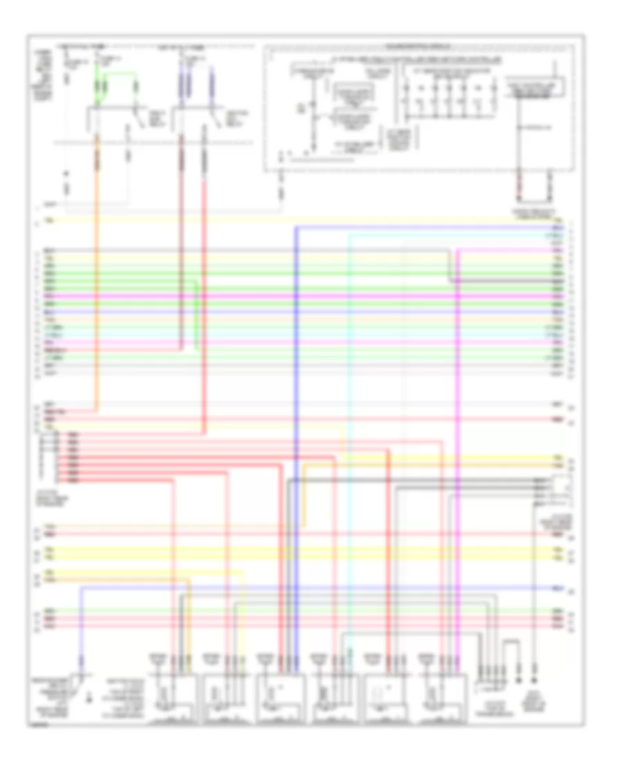
2.4L, Engine Performance Wiring Diagram (4 of 5) for Honda Accord EX 2010
List of elements for 2.4L, Engine Performance Wiring Diagram (4 of 5) for Honda Accord EX 2010:
- (left side of engine)
- (left side of transmission) a/t clutch pressure control solenoid valves
- (on exhaust manifold) a/f sensor
- (on transmission) atf temperature sensor
- (rear of engine) ect sensor 1
- (right side of transmission housing) (a/t) input shaft (mainshaft) speed sensor
- (thermal joint) s4
- (under right rear of engine compt) secondary ho2s
- A12
- B12
- Cmp sensor a (rear of engine)
- Engine mount control solenoid valve (left front of engine)
- G101
- G101 (left side of engine)
- G102 (left side of engine)
- Icm
- Ignition coils (top of engine)
- J/c c101 (left side of engine compt)
- J/c c103 (rear of engine)
- Knock sensor (left side of engine)
- Pnk
- Red
- S1 (thermal joint)
- S2 (thermal joint)
- Spark plug
- Vtc oil control solenoid valve (front of engine)
2.4L, Engine Performance Wiring Diagram (5 of 5) for Honda Accord EX 2010
List of elements for 2.4L, Engine Performance Wiring Diagram (5 of 5) for Honda Accord EX 2010:
- (left side of engine) g101
- Afs+
- Afs-
- Afshtc
- Altc
- Altf
- Altl
- Atft
- Atpd
- Atpfwd
- Atprvs
- B22
- B23
- B24
- B25
- B26
- B27
- B28
- B29
- B30
- B31
- B32
- B33
- B34
- B35
- B36
- B37
- B38
- B39
- B40
- B41
- B42
- B43
- B44
- B45
- B46
- B47
- B48
- B49
- C10
- C11
- C12
- C13
- C14
- C15
- C16
- C17
- C18
- C19
- C20
- C21
- C22
- C23
- C24
- C25
- C26
- C27
- C28
- C29
- C30
- C31
- C32
- C33
- C34
- C35
- C36
- C37
- C38
- C39
- C40
- C41
- C42
- C43
- C44
- C45
- C46
- C47
- C48
- C49
- Ckp
- Cmpa
- Cmpb
- Ecm/pcm (left front of engine compt)
- Ect1
- Etcsm+
- Etcsm-
- Iat
- Ig1
- Ig1etcs
- Igpls1
- Igpls2
- Igpls3
- Igpls4
- Inj1
- Inj2
- Inj3
- Inj4
- J/c c103 (rear of engine)
- Lg1 gnd
- Lg2 gnd
- Lsa
- Lsb
- Lsc
- Map
- Map sensor (left rear of engine)
- Mcs
- Output shaft (countershaft) speed sensor (right side of transmission housing)
- Pgmetcs
- Pnk
- Red
- Rocker arm oil control solenoid (intake) (right front of engine)
- Rocker arm oil pressure switch (exhaust) (w/ sulev/pzev) (right front of engine)
- S1 (thermal joint)
- S3 (thermal joint)
- Sg1
- Sg2
- Sg3
- Shd
- She
- Shift control solenoid valve d
- Shift control solenoid valve e
- Sho2s
- Starting/ charging system
- Throttle actuator
- Tp sensor
- Tp sensor/throttle actuator (on throttle body)
- Tpsa
- Tpsb
- Vcc1
- Vcc3
- Vg+
- Vg-
- Vtc
- Vtpswa
- Vtpswb
- Vts
- Vtsb
3.5L
3.5L, Engine Performance Wiring Diagram (1 of 6) for Honda Accord EX 2010
List of elements for 3.5L, Engine Performance Wiring Diagram (1 of 6) for Honda Accord EX 2010:
- (behind left side of front bumper) g301
- (on accelerator pedal support) app sensor
- A10
- A11
- A12
- A13
- A14
- A15
- A16
- A17
- A18
- A19
- A20
- A21
- A22
- A23
- A24
- A25
- A26
- A27
- A28
- A29
- A30
- A31
- A32
- A33
- A34
- A35
- A36
- A37
- A38
- A39
- A40
- A41
- A42
- A43
- A44
- A45
- A46
- A47
- A48
- A49
- Acc
- Acpd
- Air conditioning system
- Air conditioning system starting/charging & anti-theft systems
- Anti-theft system
- Apsa
- Apsb
- Atp-p
- Atpp
- B10
- B11
- B12
- B13
- B14
- B15
- B16
- B17
- B18
- B19
- B20
- B21
- Baro- meter sensor
- Bksw
- Bkswnc
- Brake pedal position switch (on brake pedal support)
- Canh
- Canl
- Ckpout
- Clutch pedal position switch (m/t) (on clutch pedal support)
- Cmpout
- Computer data lines system
- Cooling fans system
- Crmtcls
- Cruise control system
- Cssama
- Cssamc
- Driver's micu
- Driver's under-dash fuse/relay box (behind left kick panel)
- Ecm/pcm (left front of engine compt)
- Ect2
- Eld
- Eld unit
- Etcs control relay
- Etcsrly
- F12
- Fanh
- Fanl
- Ftp
- Fuse 10a
- Fuse 17 15a
- Fuse 18 15a
- Fuse 19 7.5a
- G101 (right front of engine)
- G302 (behind left kick panel)
- Hot at all times
- Hot in on or start
- Igp
- Igpls5
- Igpls6
- Imofpr
- Imtm vcmswc (or vtpsw) lsc
- Inj1
- Inj2
- Inj3
- Inj4
- Inj5
- Inj6
- Injector 6 (on top of left cylinder bank)
- Injectors 1, 2 & 3 (top of right cylinder bank)
- Injectors 4 & 5 (top of left cylinder bank)
- J/c c106 (right rear of engine)
- Lg3
- Lsb
- Mcs
- Mrly
- Navigation & sound systems
- Pg2
- Pgm fi main relay
- Pnk
- Power distribution system
- Pspsw
- Red
- S net
- Scs
- Sg3
- Sg4
- Sg7
- Sho2sb2
- Sls (or rvs)
- Starting/charging system
- Sts
- Subrly
- Tan
- Tpsa
- Under- hood fuse/ relay box (left rear of engine compt)
- Vbsol1
- Vbsol2
- Vbum
- Vcc3
- Vcc4
- Vcc5
- Vcc7
- Vcentb1
- Vg+
- Vg-
- Vsb1
- Vsb2
- Vssout
- Vsv
- Wen
3.5L, Engine Performance Wiring Diagram (2 of 6) for Honda Accord EX 2010
List of elements for 3.5L, Engine Performance Wiring Diagram (2 of 6) for Honda Accord EX 2010:
- (behind left kick panel) (a/t) engine mount control unit
- (lower left front of engine compt) ect sensor 2
- (lower middle front of engine compt) front engine mount control actuator
- (right rear of engine compt) psp switch
- (right rear of engine) j/c c105
- (right side of engine compt) a/c pressure sensor
- (under middle rear of vehicle) ftp sensor
- A/t
- A/t clutch pressure control solenoid valve b (top rear of transmission)
- A/t clutch pressure control solenoid valve c (top of transmission)
- Can h
- Can l
- Ckp
- Cmp
- Computer data lines system
- Front rocker arm oil pressure switch (left front of engine)
- Front secondary ho2s (b2, s2) (in left exhaust bank)
- G101 (right front of engine)
- G201 (behind right side of dash)
- G302 (behind left kick panel)
- Iat
- Ig1
- Igsol
- J/c c107 (top of transmission)
- M/t
- Maf
- Maf/iat sensor (on intake air duct)
- Pnk
- Rear engine mount control actuator (lower middle rear of engine compt)
- Rear secondary ho2s (b1, s2) (in right exhaust bank)
- Red
- Rocker arm oil pressure switch (right rear of engine)
- Scpa
- Scpc
- Solfm
- Solfp
- Solrly
- Solrm
- Solrp
- Sound systems
- System conditioning air
- Tan
3.5L, Engine Performance Wiring Diagram (3 of 6) for Honda Accord EX 2010
List of elements for 3.5L, Engine Performance Wiring Diagram (3 of 6) for Honda Accord EX 2010:
- (in left exhaust bank) front a/f sensor (b2, s1)
- (in right exhaust bank) rear a/f sensor (b1, s1)
- (right rear of engine)
- (right rear of engine) j/c c105
- (sulev/ ulev) chip resistor
- (under middle rear of vehicle, on evap control canister) evap canister vent shut valve
- A/t
- Acm control relay
- Cooling fans system
- D10
- Driver's under-dash fuse/relay box (behind left kick panel)
- Engine mount control solenoid valve (m/t) (right rear of engine)
- Evap canister purge valve (right rear of engine)
- F14
- F22
- F31
- Fuel gauge sending unit
- Fuel pump
- Fuel pump relay
- Fuel tank unit (top of fuel tank)
- Fuse 14 10a
- Fuse 7 15a
- Fuse 9 20a
- G101 (right front of engine)
- G603 (left rear of floor)
- Hot at all times
- Hot in on or start
- Instrument cluster system
- J/c c106 (right rear of engine)
- J/c c107 (top of transmission)
- M/t
- Pnk
- Red
- Remote starting control unit
- Reverse lockout solenoid (on transmission housing)
- Rocker arm oil control solenoid (under right front of engine)
- Rocker arm oil control solenoid a
- Rocker arm oil control solenoid b
- Sulev/ ulev
- Tan
- Ulev
3.5L, Engine Performance Wiring Diagram (4 of 6) for Honda Accord EX 2010
List of elements for 3.5L, Engine Performance Wiring Diagram (4 of 6) for Honda Accord EX 2010:
- 10v stabilizer circuit
- 5v stabilizer circuit/controller area network controller
- A/t gear position dimming circuit
- A/t gear position indicator drive circuit
- Compulsory turning off circuit
- Compulsory turning on circuit
- Computer data lines system
- Fail safe circuit
- Fast controller area network transceiver
- Fuse 13 15a
- Fuse 14 15a
- Fuse 15 10a
- G101 (right front of engine)
- Gauge control module
- Hot at all times
- Icm
- Ignition coil relay
- Ignition coils (1, 2 & 3: top of right cylinder bank) (4, 5 & 6: top of left cylinder bank)
- J/c c105 (right rear of engine)
- J/c c106 (right rear of engine)
- J/c c107 (top of transmission)
- Mil ind
- Pgm fi sub relay
- Pnk
- Rear rocker arm oil pressure switch (a/t) (right rear of engine)
- Red
- Spark plug
- Tan
- Under- hood fuse/ relay box (left rear of engine compt)
- Warning drive circuit
3.5L, Engine Performance Wiring Diagram (5 of 6) for Honda Accord EX 2010
List of elements for 3.5L, Engine Performance Wiring Diagram (5 of 6) for Honda Accord EX 2010:
- (left rear of engine) ect sensor 1
- (left rear of engine) egr valve & egr valve position sensor
- (on transmission) atf temperature sensor
- (right front of engine) g101
- (right side of transmission housing) input shaft (mainshaft) speed sensor
- (top of trans) j/c c107
- (top of transmission) j/c c108
- (under right front of engine) rocker arm oil pressure sensor
- 2nd clutch transmission fluid pressure switch (left side of transmission)
- 3rd clutch transmission fluid pressure switch (left rear of transmission)
- G101 (right front of engine)
- J/c c107 (top of transmission)
- J/c c108 (top of trans- mission)
- Map sensor (rear of engine)
- Oil pressure switch (under right front of engine)
- Output shaft (countershaft) speed sensor (right side of transmission housing)
- Pnk
- Red
- Shift control solenoid valve c
- Shift control solenoid valve d
- Starting/ charging system
- Tan
- Transmission range switch (on transmission)
3.5L, Engine Performance Wiring Diagram (6 of 6) for Honda Accord EX 2010
List of elements for 3.5L, Engine Performance Wiring Diagram (6 of 6) for Honda Accord EX 2010:
- (front of engine) (a/t) rocker arm oil control solenoid c
- (front of engine) imt actuator
- (left side of transmission) 4th clutch transmission fluid pressure switch
- (or vts)
- (top rear of transmission) a/t clutch pressure control solenoid valve a
- A/t
- Afshtcb1
- Afshtcb2
- Altc
- Altf
- Altl
- Atft
- Atp2-1
- Atpd
- Atpd3
- Atpfwd
- Atpn
- Atpr
- Atprvs
- B22
- B23
- B24
- B25
- B26
- B27
- B28
- B29
- B30
- B31
- B32
- B33
- B34
- B35
- B36
- B37
- B38
- B39
- B40
- B41
- B42
- B43
- B44
- B45
- B46
- B47
- B48
- B49
- C10
- C11
- C12
- C13
- C14
- C15
- C16
- C17
- C18
- C19
- C20
- C21
- C22
- C23
- C24
- C25
- C26
- C27
- C28
- C29
- C30
- C31
- C32
- C33
- C34
- C35
- C36
- C37
- C38
- C39
- C40
- C41
- C42
- C43
- C44
- C45
- C46
- C47
- C48
- C49
- Ckp
- Ckp sensor (under right front of engine)
- Cmp
- Cmp sensor (right front of engine)
- Cssa
- Cssb
- Cssc
- Ecm/pcm (left front of engine compt)
- Ect1
- Egr
- Egrp
- Etcsm+
- Etcsm-
- G101 (right front of engine)
- Iat
- Ig1
- Ig1etcs
- Igpls1
- Igpls2
- Igpls3
- Igpls4
- Ip b1
- Ip b2
- J/c c107 (top of transmission)
- Knock sensor (left side of engine)
- Lg1
- Lg2
- Lsa
- M/t
- Map
- Mt+
- Mt-
- Op2sw
- Op3sw
- Op4sw
- Opsw
- Pcs
- Pg1
- Pgmetcs
- Pnk
- Poil
- Red
- Sg1
- Sg2
- Sg5
- Sg6
- Sha
- Shb
- Shc
- Shd
- Shift control solenoid valve a
- Shift control solenoid valve b
- Sho2sb1
- So2shtcb1
- So2shtcb2
- Starting/ charging system
- Tan
- Tp sensor/throttle actuator (on throttle body)
- Tpsb
- Vcc1
- Vcc6
- Vcc7
- Vcentb2
- Vcmswb
- Vlblb1
- Vlblb2