ENGINE PERFORMANCE
1.5L
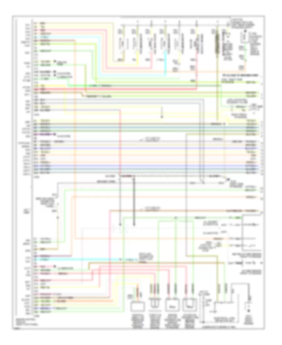
1.5L VTEC, Engine Performance Wiring Diagrams (1 of 2) for Honda Civic VX 1995

List of elements for 1.5L VTEC, Engine Performance Wiring Diagrams (1 of 2) for Honda Civic VX 1995:
- (center of engine)
- (right side
- (right side of engine)
- A/c system
- A10
- A11
- A12
- A13
- A14
- A15
- A16
- A17
- A18
- A19
- A20
- A21
- A22
- A23
- A24
- A25
- A26
- Acc
- Acs
- Altc
- Alternator
- Altf
- B10
- B11
- B12
- B13
- B14
- B15
- B16
- Bksw
- Braided wire
- Braided wires
- C404
- C405
- C406
- Calif
- Ckp m
- Ckp p
- Clsw
- Connector (right kick panel)
- Control valve
- Cyp m
- Cyp p
- D10
- D11
- D12
- D13
- D14
- D15
- D16
- D17
- D18
- D19
- D20
- D21
- D22
- Data link
- Dlc
- Ect
- Egrl
- Engine control module (right kick panel)
- Engine coolant temperature sensor (right front of engine)
- Evaporative emission
- Exc. calif
- Exhaust gas recirculation valve lift sensor (right side of engine)
- Fanc
- Fans
- Flr1
- Fuel injector #1
- Fuel injector #2
- Fuel injector #3
- Fuel injector #4
- G120
- G120 (right side of engine)
- G120 of engine)
- Heated oxygen sensor (california) (right front of engine)
- Heated oxygen sensor (except calif) (right front of engine)
- Htcntl
- Iacv
- Iat
- Icm 1
- Idle air
- Igp1
- Igp2
- Inj1
- Inj2
- Inj3
- Inj4
- Intake air temperature sensor (center rear of engine)
- Ip+
- Ip-, vs-
- Junction connector (c125) (left rear corner of engine compt)
- Label
- Lg1
- Lg2
- Manifold absolute pressure sensor (middle of engine)
- Map
- Mil
- Nca
- Not used
- Pcs
- Pg1
- Pg2
- Pnk
- Pspsw
- Purge control solenoid valve
- Red
- Scs
- Service check connector (right kick panel)
- Sg1
- Sg2
- Sil
- Sts
- Tdc m
- Tdc p
- Throttle position sensor (center rear of engine)
- Tps
- Vbu
- Vcc1
- Vcc2
- Vs+
- Vss
- Vtec solenoid valve (right side of engine)
- Vtm
- Vts
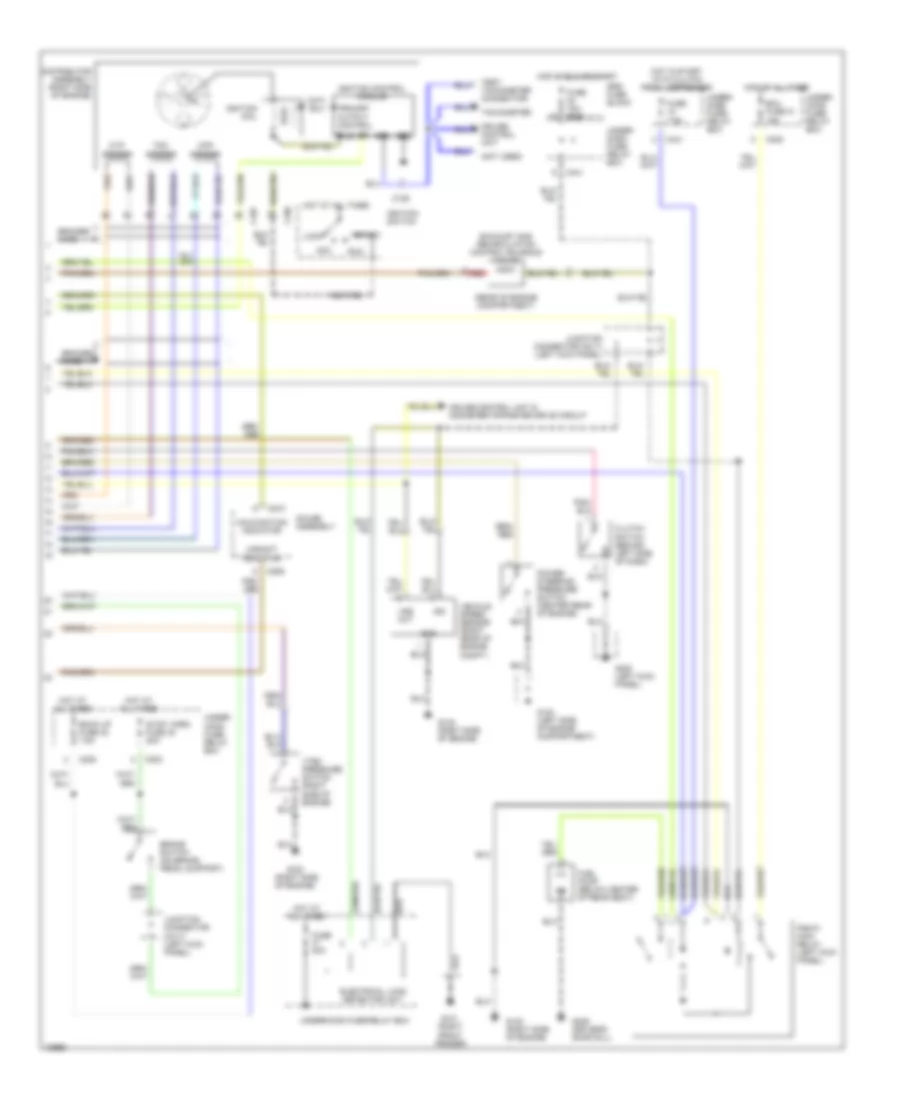
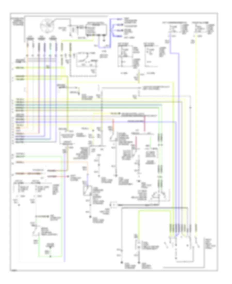
1.5L VTEC, Engine Performance Wiring Diagrams (2 of 2) for Honda Civic VX 1995
List of elements for 1.5L VTEC, Engine Performance Wiring Diagrams (2 of 2) for Honda Civic VX 1995:
- (not used)
- (rear of engine compartment)
- (right front fender)
- (right side of engine)
- Acc
- Back up fuse 32 7.5a
- Braided wire
- Brake switch (on brake pedal support)
- C106
- C107
- C202
- C205
- C441
- C509
- C510
- Ckp sensor
- Clutch switch (behind left side of dash)
- Cruise control unit
- Cruise control unit & odometer/tripmeter drive circuit
- Cyp sensor
- Distributor assembly (right side of engine)
- Ecu fuse 31 15a
- Electrical load detector unit
- Exhaust gas recirculation control solenoid valve
- Fuel pump (below center of rear seat)
- Fuse 15a c922
- Fuse 7.5a
- Fuse 80a
- G100 (left side of engine compartment)
- G101
- G120
- G120 (right side of engine)
- G200 (left kick panel)
- G309 (driver's door sill)
- Gauge assembly
- Gnd
- Hot at all times
- Hot in run or start
- Hot in start with clutch pedal depressed
- Ign
- Ignition coil
- Ignition control module
- Ignition switch
- Junction connector (c417) (left kick panel)
- Lock
- Malfunction indicator
- Pgm-fi main relay (left kick panel)
- Power steering pressure switch (center rear of engine)
- Primary output control
- Pwr
- Red
- Rpm
- Run
- Srs fuse block
- Start
- Stop, horn fuse 42 20a
- Tachometer
- Tdc sensor
- Test tachometer connector)
- Under- dash fuse/ relay box
- Under- hood fuse/ relay box
- Underhood fuse/relay box
- Upshift indicator
- Vehicle speed sensor (right rear of engine compt.)
- Vss out
- Vtec pressure switch (right side of engine)
1.5L, Engine Performance Wiring Diagrams (1 of 2) for Honda Civic VX 1995
List of elements for 1.5L, Engine Performance Wiring Diagrams (1 of 2) for Honda Civic VX 1995:
- (center of engine)
- (rear of engine)
- (right front fender)
- (right front of engine)
- (right side
- (right side of engine)
- A/c system
- A10
- A11
- A12
- A13
- A14
- A15
- A16
- A17
- A18
- A19
- A20
- A21
- A22
- A23
- A24
- A25
- A26
- Acc
- Acs
- All except cx 49-state
- Altc
- Alternator
- Altf
- Atlsa
- Atlsb
- Atp d3
- Atp d4
- Atp/clsw
- B10
- B11
- B12
- B13
- B14
- B15
- B16
- Bksw
- Braided wire
- Braided wires
- C404
- C405
- C406
- Ckp m
- Ckp p
- Connector (c125)
- Control valve
- Cooling fans
- Cx 49-state
- Cyp m
- Cyp p
- D10
- D11
- D12
- D13
- D14
- D15
- D16
- D17
- D18
- D19
- D20
- D21
- D22
- Data link connector (right kick
- Dlc
- Ect
- Electrical load detector unit
- Engine control module (right kick panel)
- Engine coolant temperature sensor (right front of engine)
- Evaporative emission
- Fanc
- Flr1
- From
- Fuel injector #1
- Fuel injector #2
- Fuel injector #3
- Fuel injector #4
- Fuse 80a
- G101
- G120
- G120 of engine)
- Heated oxygen sensor (all except cx 49- state)
- Heated oxygen sensor (front of engine)
- Hot at all times
- Iacv
- Iat
- Icm 1
- Idle air
- Igp1
- Igp2
- Inj1
- Inj2
- Inj3
- Inj4
- Intake air temperature sensor (center rear of engine)
- Junction
- Junction connector (c125) (left rear corner of engine compt)
- Lg1
- Lg2
- Lock up control solenoid valves
- M/t (usa cx) & a/t only
- Manifold absolute pressure sensor (middle of engine)
- Map
- Mil
- Nca
- Not used
- O2s
- O2shtc
- Oxygen sensor (front of engine)
- Panel)
- Pcs
- Pg1
- Pg2
- Pnk
- Pspsw
- Purge control solenoid valve
- Red
- Scs
- Service check connector (right kick panel)
- Sg1
- Sg2
- Slu/sil
- Sts
- Tdc m
- Tdc p
- Throttle position sensor center rear of engine)
- Tps
- Underhood fuse/relay box
- Vbu
- Vcc1
- Vcc2
- Vss
- Vtec solenoid valve (vtec engines only) (right side of engine)
- Vtm
- Vts
1.5L, Engine Performance Wiring Diagrams (2 of 2) for Honda Civic VX 1995
List of elements for 1.5L, Engine Performance Wiring Diagrams (2 of 2) for Honda Civic VX 1995:
- (not used)
- (right side of engine)
- (usa cx)
- (vtec engines only)
- A/t
- A/t gear position indicator
- A/t gear position switch (below center console)
- Acc
- Back up fuse 32 7.5a
- Braided wire
- Brake switch (on brake pedal support)
- C106
- C107
- C202
- C205
- C441
- C509
- C510
- C512
- Ckp sensor
- Clutch switch (behind left side of dash)
- Cruise control
- Cruise control unit
- Cruise control unit & odometer/tripmeter drive circuit
- Cyp sensor
- Distributor assembly (right side of engine)
- Ecu fuse 31 15a
- Fuel pump (below center of rear seat)
- Fuse 15a
- Fuse 15a c922
- Fuse 7.5a
- G100 (left side of engine compartment)
- G120 (right side of engine)
- G200 (left kick panel)
- G309 (driver's door sill)
- Gauge assembly
- Gnd
- Hot at all times
- Hot in run or start
- Hot w/ engine cranking
- Ign
- Ignition coil
- Ignition control module
- Ignition switch
- Junction connector (c417) (left kick panel)
- Key interlock switch
- Lock
- M/t
- M/t(usa cx)
- Malfunction indicator
- Pgm-fi main relay (left kick panel)
- Power steering pressure switch (center rear of engine)
- Primary output control
- Pwr
- Rpm
- Shift interlock system
- Srs fuse block
- Start
- Stop, horn fuse 42 20a
- Tachometer
- Tdc sensor
- Test tachometer connector)
- Under- dash fuse/ relay box
- Under- hood fuse/ relay box
- Upshift indicator
- Vehicle speed sensor (right rear of engine compartment)
- Vss out
- Vtec pressure switch
- W/ srs
- W/o srs
1.6L
1.6L VTEC, Engine Performance Wiring Diagrams (1 of 2) for Honda Civic VX 1995
List of elements for 1.6L VTEC, Engine Performance Wiring Diagrams (1 of 2) for Honda Civic VX 1995:
- (center of engine)
- (rear of engine)
- (right front fender)
- (right front of engine)
- (right side
- (right side of engine)
- A/c system
- A10
- A11
- A12
- A13
- A14
- A15
- A16
- A17
- A18
- A19
- A20
- A21
- A22
- A23
- A24
- A25
- A26
- Acc
- Acs
- All except cx 49-state
- Altc
- Alternator
- Altf
- Atlsa
- Atlsb
- Atp d3
- Atp d4
- Atp/clsw
- B10
- B11
- B12
- B13
- B14
- B15
- B16
- Bksw
- Braided wire
- Braided wires
- C404
- C405
- C406
- Ckp m
- Ckp p
- Connector (c125)
- Control valve
- Cooling fans
- Cx 49-state
- Cyp m
- Cyp p
- D10
- D11
- D12
- D13
- D14
- D15
- D16
- D17
- D18
- D19
- D20
- D21
- D22
- Data link connector (right kick
- Dlc
- Ect
- Electrical load detector unit
- Engine control module (right kick panel)
- Engine coolant temperature sensor (right front of engine)
- Evaporative emission
- Fanc
- Flr1
- From
- Fuel injector #1
- Fuel injector #2
- Fuel injector #3
- Fuel injector #4
- Fuse 80a
- G101
- G120
- G120 of engine)
- Heated oxygen sensor (all except cx 49- state)
- Heated oxygen sensor (front of engine)
- Hot at all times
- Iacv
- Iat
- Icm 1
- Idle air
- Igp1
- Igp2
- Inj1
- Inj2
- Inj3
- Inj4
- Intake air temperature sensor (center rear of engine)
- Junction
- Junction connector (c125) (left rear corner of engine compt)
- Lg1
- Lg2
- Lock up control solenoid valves
- M/t (usa cx) & a/t only
- Manifold absolute pressure sensor (middle of engine)
- Map
- Mil
- Nca
- Not used
- O2s
- O2shtc
- Oxygen sensor (front of engine)
- Panel)
- Pcs
- Pg1
- Pg2
- Pnk
- Pspsw
- Purge control solenoid valve
- Red
- Scs
- Service check connector (right kick panel)
- Sg1
- Sg2
- Slu/sil
- Sts
- Tdc m
- Tdc p
- Throttle position sensor center rear of engine)
- Tps
- Underhood fuse/relay box
- Vbu
- Vcc1
- Vcc2
- Vss
- Vtec solenoid valve (vtec engines only) (right side of engine)
- Vtm
- Vts
1.6L VTEC, Engine Performance Wiring Diagrams (2 of 2) for Honda Civic VX 1995
List of elements for 1.6L VTEC, Engine Performance Wiring Diagrams (2 of 2) for Honda Civic VX 1995:
- (not used)
- (right side of engine)
- (usa cx)
- (vtec engines only)
- A/t
- A/t gear position indicator
- A/t gear position switch (below center console)
- Acc
- Back up fuse 32 7.5a
- Braided wire
- Brake switch (on brake pedal support)
- C106
- C107
- C202
- C205
- C441
- C509
- C510
- C512
- Ckp sensor
- Clutch switch (behind left side of dash)
- Cruise control
- Cruise control unit
- Cruise control unit & odometer/tripmeter drive circuit
- Cyp sensor
- Distributor assembly (right side of engine)
- Ecu fuse 31 15a
- Fuel pump (below center of rear seat)
- Fuse 15a
- Fuse 15a c922
- Fuse 7.5a
- G100 (left side of engine compartment)
- G120 (right side of engine)
- G200 (left kick panel)
- G309 (driver's door sill)
- Gauge assembly
- Gnd
- Hot at all times
- Hot in run or start
- Hot w/ engine cranking
- Ign
- Ignition coil
- Ignition control module
- Ignition switch
- Junction connector (c417) (left kick panel)
- Key interlock switch
- Lock
- M/t
- M/t(usa cx)
- Malfunction indicator
- Pgm-fi main relay (left kick panel)
- Power steering pressure switch (center rear of engine)
- Primary output control
- Pwr
- Rpm
- Shift interlock system
- Srs fuse block
- Start
- Stop, horn fuse 42 20a
- Tachometer
- Tdc sensor
- Test tachometer connector)
- Under- dash fuse/ relay box
- Under- hood fuse/ relay box
- Upshift indicator
- Vehicle speed sensor (right rear of engine compartment)
- Vss out
- Vtec pressure switch
- W/ srs
- W/o srs