ENGINE PERFORMANCE
2.4L
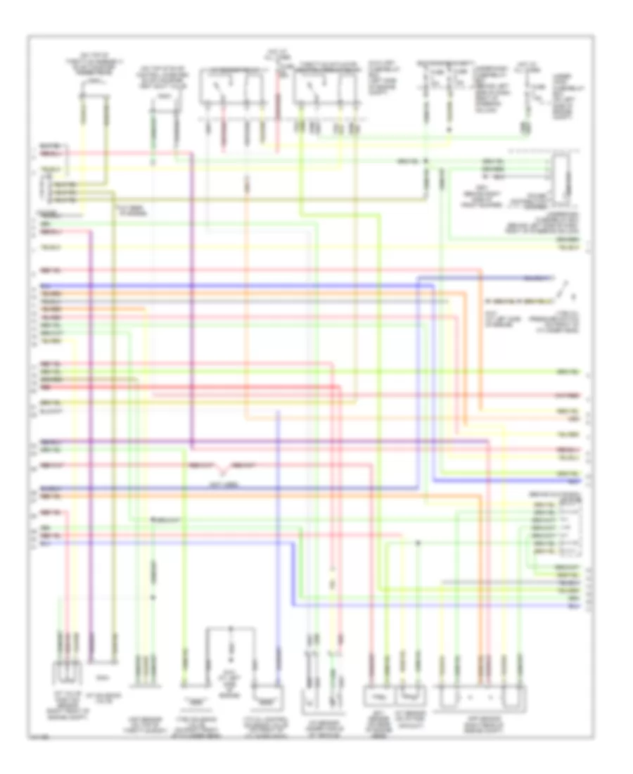
2.4L, Engine Performance Wiring Diagram (1 of 4) for Honda CR-V EX 2005

List of elements for 2.4L, Engine Performance Wiring Diagram (1 of 4) for Honda CR-V EX 2005:
- (a/t)
- (at left side of engine) g101
- (at top of engine)
- (behind glove box)
- (behind glove box) j/c c105
- (behind left side of dash, right of steering column) under-dash fuse/relay box
- (behind right side of dash)
- (m/t)
- (middle of engine)
- (on rear of cylinder head) cmp sensor a
- (top of fuel tank) fuel tank unit
- A10
- A11
- A12
- A13
- A14
- A15
- A16
- A17 a18
- A19
- A20
- A21
- A22
- A23
- A24
- A25
- A26
- A27
- A28
- A29
- A30
- A31
- Afs (+)
- Afs (-)
- Afshtc
- All times
- Altc
- Altf
- Altl
- Apsa
- Apsb
- Auxiliary fuse/relay box (left side of engine compt)
- B10
- B11
- B12
- B13
- B14
- B15
- B16
- B17
- B18
- B19
- B20
- B21
- B22
- B23
- B24
- Barometer sensor
- Ckp
- Ckp sensor (on lower left front of engine, near crankshaft pulley)
- Cmp sensor b (on rear of cylinder head)
- Cmpa
- Cmpb
- Cruise control system
- D10
- D11
- D12
- D13
- D14
- D15
- D16
- D17
- Dbwrly
- Ecm/pcm (behind right side of dash)
- Ect
- Fuel injectors
- Fuel pump
- Fuse 15a
- G101
- G101 (middle of engine)
- G551 (under driver's seat)
- Hot at
- Iat
- Icm
- Ignition coil 1
- Ignition coil 2
- Ignition coil 3
- Ignition coil 4
- Ignition coil relay
- Igp1
- Igp2
- Igpls1
- Igpls2
- Igpls3
- Igpls4
- Imt
- Imtvps
- Inj1
- Inj2
- Inj3
- Inj4
- J/c c103 (at rear of engine)
- Lg1
- Lg2
- Map
- Pcs
- Pg1
- Pg2
- Pgm-f1 main relay 1
- Pgm-f1 main relay 2
- Red
- Sedf
- Sefd
- Setind
- Sg1
- Sg2
- Starting/ charging system
- Vcc1
- Vcc2
- Vss(m/t) nc (a/t)
- Vtc
- Vtpsw
- Vts
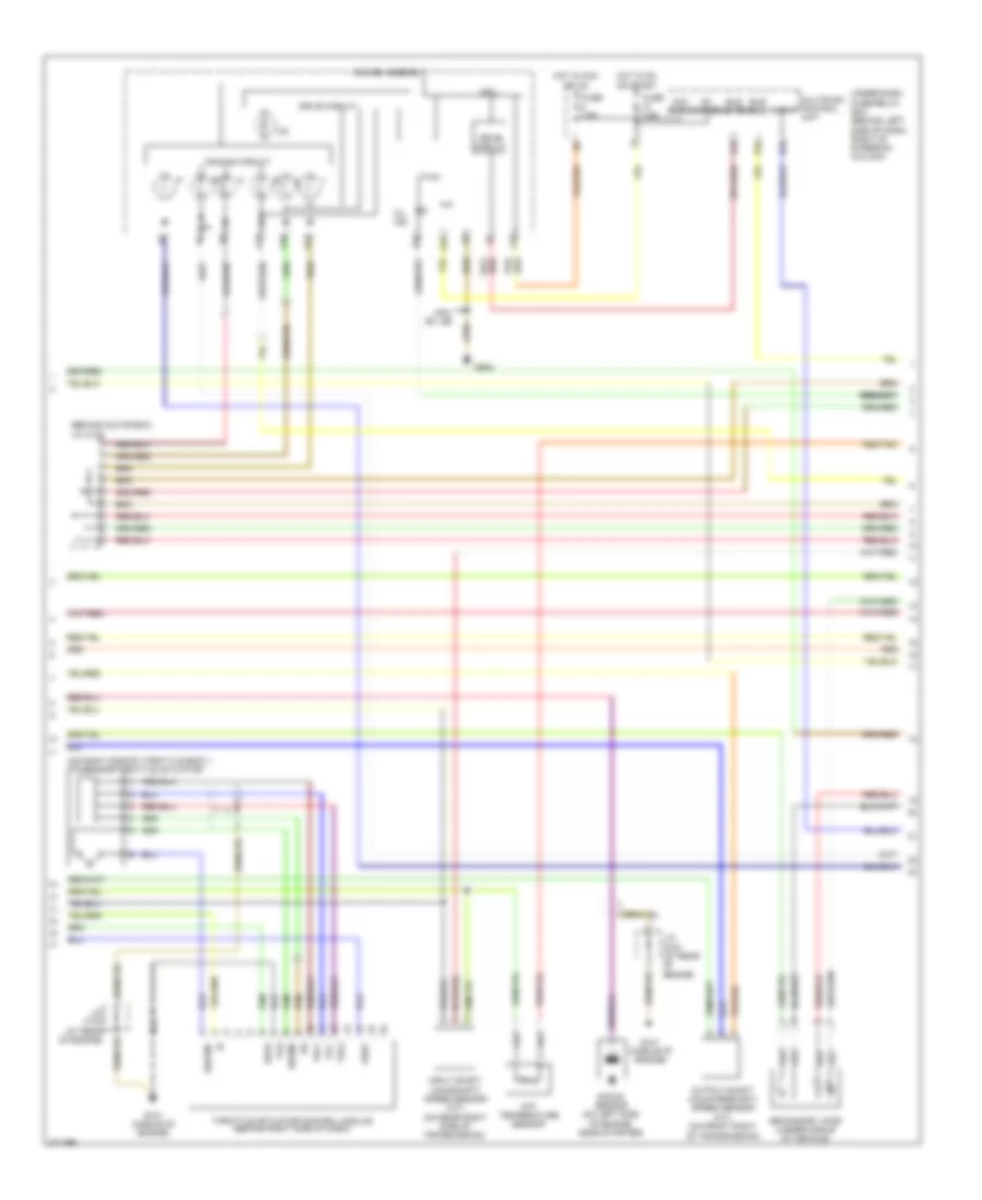
2.4L, Engine Performance Wiring Diagram (2 of 4) for Honda CR-V EX 2005
List of elements for 2.4L, Engine Performance Wiring Diagram (2 of 4) for Honda CR-V EX 2005:
- (at rear of engine)
- (behind glove box) j/c c105
- (not used)
- (on top of evap control canister) evap canister vent shut valve
- (on top of throttle assembly) evap canister purge valve
- A/f sensor (under middle of vehicle)
- A/f sensor relay
- Air duct)
- App sensor (right rear of engine compt)
- Auxiliary fuse/relay box (left side of engine compt)
- C10
- Ect sensor (on rear of engine head)
- Eld unit
- Fuse 10a
- Fuse 20a
- Fuse 7.5a
- G101 (at left side of engine)
- G201 (behind right side of front bumper)
- Hot at all times
- Hot in on or start
- Iat sensor (on intake
- Imt solenoid valve
- Imt valve position sensor (right front of engine compt)
- Map sensor (on top of throttle body)
- Power distribution system
- Red
- Throttle actuator control module relay
- Under- hood fuse/relay box (on left side of engine compt)
- Under-dash fuse/relay box (behind left side of dash, right of steering column)
- Vtc oil control solenoid valve (on front of cylinder head)
- Vtec oil pressure switch (on front of cylinder head)
- Vtec solenoid valve (on right front of cylinder head)
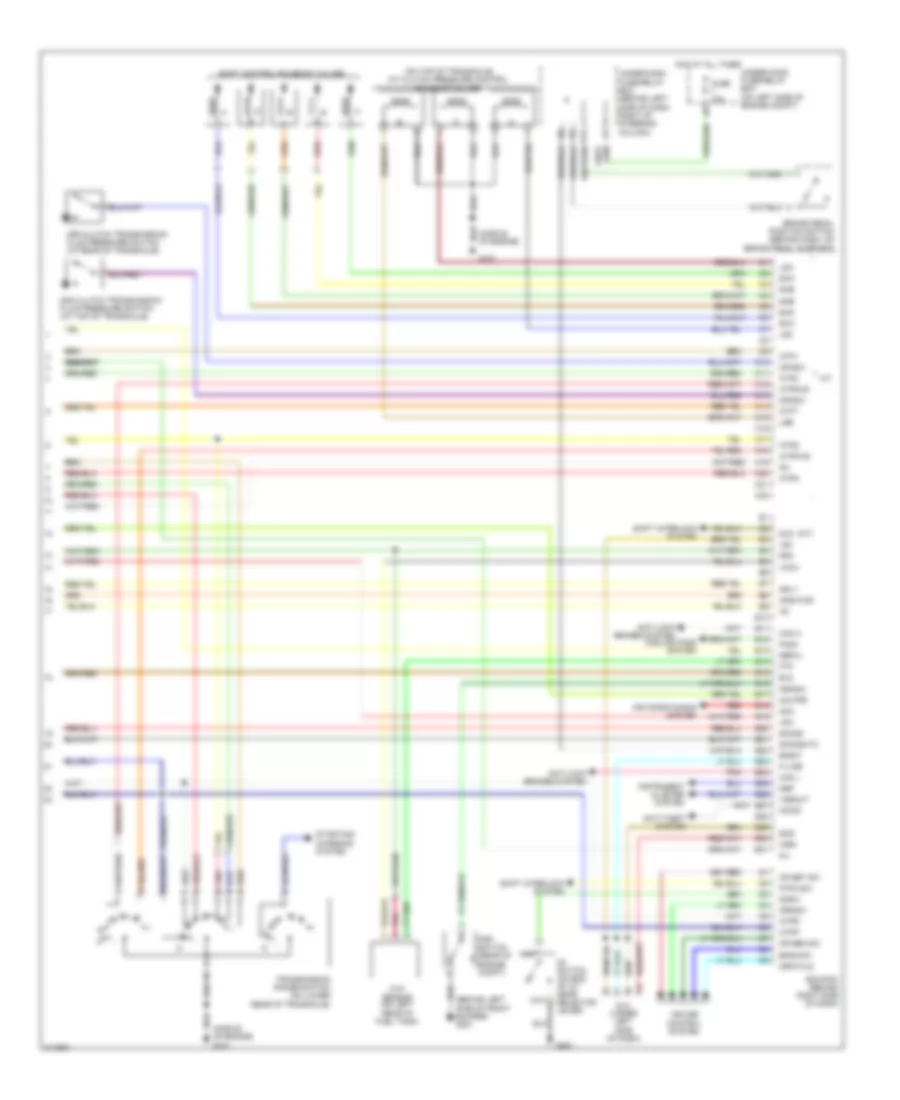
2.4L, Engine Performance Wiring Diagram (3 of 4) for Honda CR-V EX 2005
List of elements for 2.4L, Engine Performance Wiring Diagram (3 of 4) for Honda CR-V EX 2005:
- (behind glove box)
- (on right side of throttle body.) tp/sensor/throttle actuator
- A13
- A14
- A15
- A16
- A18
- Acc radio
- Atf temperature sensor
- Atp-p
- B20
- Bus (ecu)
- Bus meter
- Cpu
- Dbw m+
- Dbwm-
- Dimming circuit
- Drive circuit
- E10
- Fuse 7.5a
- G101 (middle of engine)
- G502
- Gauge assembly
- Hot in acc or on
- Hot in on or start
- Ig1 meter
- Input shaft (mainshaft) speed sensor (a/t) (on rear right side of transmission)
- J/c c103 (at rear of engine)
- J/c c105
- K10
- Knock sensor (on left side of engine, near starter)
- Mil ind
- Multiplex control unit
- Output shaft (countershaft) speed sensor (a/t) (on front right of transmission)
- Pg2
- Secondary ho2s (under middle of vehicle)
- Sedf
- Sefd
- Thl1
- Thl2
- Throttle actuator control module (behind right side of dash)
- Under-dash fuse/relay box (behind left side of dash, right of steering column)
- Usa: ex, se
- Vcc
2.4L, Engine Performance Wiring Diagram (4 of 4) for Honda CR-V EX 2005
List of elements for 2.4L, Engine Performance Wiring Diagram (4 of 4) for Honda CR-V EX 2005:
- anti-lock brakes system
- (a/t)
- (behind left side of front bumper) g301
- (middle of engine)
- (middle of engine) g101
- (on top of transaxle) a/t clutch pressure control solenoid valves
- 2nd clutch transmission fluid pressure switch (at top of transaxle)
- 3rd clutch transmission fluid pressure switch (at rear of transaxle)
- A/t
- Acc
- Afshtcr
- Air conditioning system
- Anti-lock brakes system
- Anti-theft system
- Atft
- Atp1
- Atp2
- Atpd
- Atpfwd
- Atpn
- Atpp
- Atpr
- Atprvs
- Bksw
- Bkswnc
- Brake pedal position switch (behind dash, on brake pedal support)
- C10
- C11
- C12
- C13
- C14
- C15
- C16
- C17
- C18
- C19
- C20
- C21
- C22
- Can h
- Can l
- Cooling fans system
- Cr res sw
- Cr set sw
- Crmsw
- Crmtcls
- Cruise control system
- D3 switch (on end of a/t gear selector lever)
- D3sw
- Dlc (under left side of dash)
- E10
- E11
- E12
- E13
- E14
- E15
- E16
- E17
- E18
- E19
- E20
- E21
- E22
- E23
- E24
- E25
- E26
- E27
- E28
- E29
- E30
- E31
- Ecm/pcm (behind right side of dash)
- Eld
- Fanc
- Ftp
- Ftp sensor (on left rear of fuel tank)
- Fuse 15a
- G101
- G451
- Hot at all times
- Ig1
- Imo fpr
- Imocd
- Instrument cluster system
- K-line
- Lg3
- Lsa
- Lsb
- Lsc
- Mil
- Mrly
- Nep
- O12
- Op2sw
- Op3sw
- P-pin sw
- Pnk
- Psp switch (rear of engine compt)
- Pspsw
- Red
- Scs
- Sefmj
- Sg3
- Sha
- Shb
- Shc
- Shd
- She
- Shift control solenoid valves
- Shift interlock system
- Sho2s
- Sho2shtc
- Sls
- Starting/ charging system
- Transmission range switch (on lower rear of transaxle)
- Under-dash fuse/relay box (behind left side of dash, right of steering column)
- Under-hood fuse/relay box (on left side of engine compt)
- Vcc3
- Vssout
- Vsv
- Wen