ENGINE PERFORMANCE
2.0L
2.0L, Engine Performance Wiring Diagrams (1 of 3) for Honda CR-V LX 1997

List of elements for 2.0L, Engine Performance Wiring Diagrams (1 of 3) for Honda CR-V LX 1997:
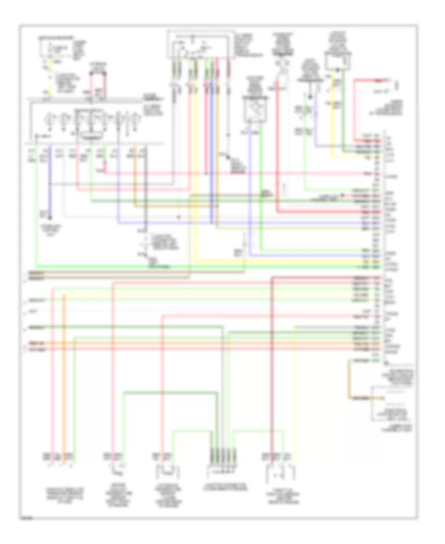
2.0L, Engine Performance Wiring Diagrams (2 of 3) for Honda CR-V LX 1997
List of elements for 2.0L, Engine Performance Wiring Diagrams (2 of 3) for Honda CR-V LX 1997:
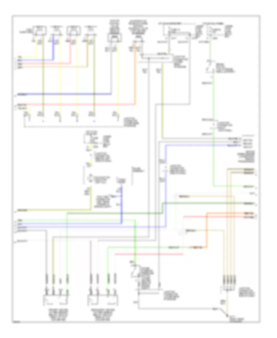
2.0L, Engine Performance Wiring Diagrams (3 of 3) for Honda CR-V LX 1997
List of elements for 2.0L, Engine Performance Wiring Diagrams (3 of 3) for Honda CR-V LX 1997: