ENGINE PERFORMANCE
1.3L HYBRID
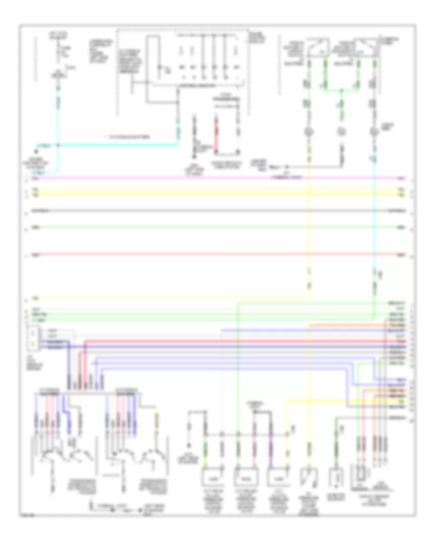
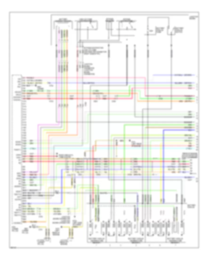
1.3L Hybrid, Engine Controls Wiring Diagram (1 of 5) for Honda Insight EX 2011

List of elements for 1.3L Hybrid, Engine Controls Wiring Diagram (1 of 5) for Honda Insight EX 2011:
- (not used)
- (right front of engine compt) a/c pressure sensor
- (right side of fuel tank) evap canister vent shut valve
- (under right front of engine compt) ect sensor 2
- A/f sensor relay
- Acc
- Acpd
- Air conditioning system
- Anti-theft system
- App sensor (left side of dash)
- Apsa
- Apsb
- B19
- B25
- Barometer sensor
- Bksw
- Bkswnc
- Brake booster pressure sensor a (left rear of engine compt)
- Brake booster pressure sensor b (left rear of engine compt)
- C103
- C302
- C305
- Canh
- Canl
- Computer data lines system
- Cooling fans system
- Ect2
- Eld
- Eld unit
- Etcsrly
- Fanh
- Fanl
- Ftp
- Ftp sensor (right side of fuel tank)
- Fuse 10a
- Fuse 7.5a
- G501 (left side of dash)
- Hot at all times
- Hot in on or start
- Igp1
- Igp2
- Ima circuit
- Imacanh
- Imacanl
- Imofpr
- J/c c306 (left side of dash)
- Mpnon1
- Mrly
- Nep
- Pcm (left front of engine compt)
- Pnk
- Power distribution system
- Red
- S-net 5v
- S6 (thermal joint)
- Scs
- Sdnp
- Sg4
- Sg5
- Sg6
- Shift interlock system electronic power steering system sound & navigation systems
- Sls
- Starting/charging system
- Starting/charging system cruise control system
- Stc
- Sts
- Subrly
- Supp
- Under-dash fuse/relay box (under left side of dash)
- Vbsol
- Vcc4
- Vcc5
- Vcc6
- Vssout
- Vsv
- Wen
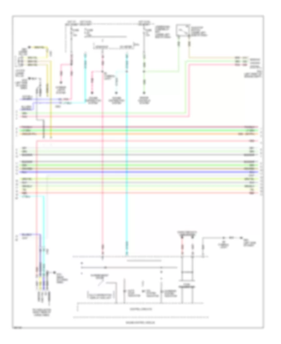
1.3L Hybrid, Engine Controls Wiring Diagram (2 of 5) for Honda Insight EX 2011
List of elements for 1.3L Hybrid, Engine Controls Wiring Diagram (2 of 5) for Honda Insight EX 2011:
- (center of dash)
- (left rear of engine) g101
- (thermal joint)
- (thermal joint) s2
- (w/ paddle shifters) sequential sport shift mode shift indicator
- B14
- B15
- C106
- C12
- C14
- C15
- C302
- Cable reel
- Computer data lines system
- Control circuits
- Cvt clutch pressure control solenoid valve
- Cvt drive pulley pressure control solenoid valve
- Cvt driven pulley pressure control solenoid valve
- F-can transceiver
- Fuse 7.5a
- G101 (left rear of engine)
- G501 (left side of dash)
- G502
- Gauge control module
- Hot in on or start
- Iat sensor
- Ig1 meter
- Inhibitor solenoid
- J/c c104 (rear of engine)
- Maf sensor
- Maf/iat sensor (on air intake hose)
- Micu
- Mil ind
- Oil pressure switch (lower left side of engine)
- Paddle shifter (+) (upshift switch) (if equipped)
- Paddle shifter (-) (downshift switch) (if equipped)
- Pnk
- Power distribution systems
- Red
- S11 (thermal joint)
- Shifters
- Steering wheel
- Transmission range switch (on transaxle housing)
- Under-dash fuse/relay box (under left side of dash)
- Used) (not
- W/ paddle
- W/o paddle
- W/o paddle shifters
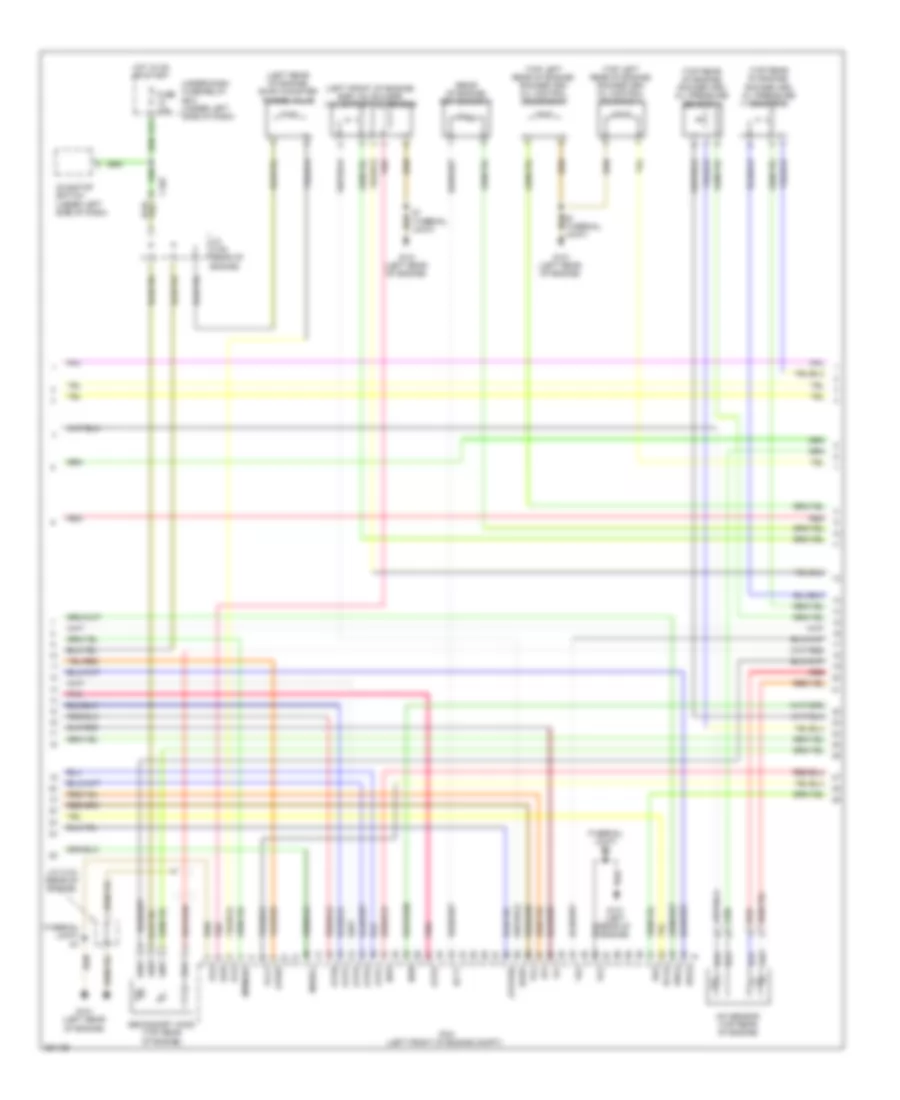
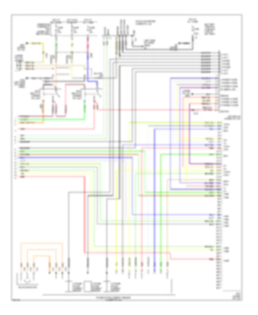
1.3L Hybrid, Engine Controls Wiring Diagram (3 of 5) for Honda Insight EX 2011
List of elements for 1.3L Hybrid, Engine Controls Wiring Diagram (3 of 5) for Honda Insight EX 2011:
- (left front of engine) egr valve & egr valve position sensor
- (left rear of engine) evap canister purge valve
- (rear of engine) ect sensor 1
- (thermal joint)
- (thermal joint) s2
- (top left rear of engine) rocker arm oil control solenoid a
- (top left rear of engine) rocker arm oil control solenoid b
- (top rear of engine) rocker arm oil pressure sensor a
- (top rear of engine) rocker arm oil pressure sensor b
- A/f sensor (top rear of engine)
- Atpd
- Atpfwd
- Atpl
- Atpn
- Atpp
- Atpr
- Atps
- B17
- C103
- Dnls
- Drls
- Ect1
- Egr
- Egrp
- Fuse 10a
- G101 (left rear of engine)
- Hot in on or start
- Iat
- Idle stop switch (under left side of dash)
- Inhsol
- J/c c104 (rear of engine)
- J/c c105 (rear of engine)
- Mpmon2
- Ndn
- Ndr
- Opsw
- Pcm (left front of engine compt)
- Pcs
- Pg1
- Pg2
- Pnk
- Red
- S1 (thermal joint)
- Scls
- Secondary ho2s (top rear of engine)
- Sg2
- Under-dash fuse/relay box (under left side of dash)
- Vcc2
- Vel
- Vg+
- Vg-
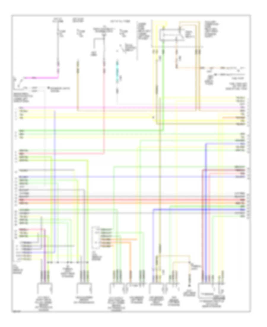
1.3L Hybrid, Engine Controls Wiring Diagram (4 of 5) for Honda Insight EX 2011
List of elements for 1.3L Hybrid, Engine Controls Wiring Diagram (4 of 5) for Honda Insight EX 2011:
- (not used)
- Auxiliary under-hood fuse/ relay box (left front of engine compt)
- B14
- B18
- B28
- Brake pedal position switch (under left side of dash)
- C101
- C103
- C302
- C407
- Ckp sensor (lower right front of engine)
- Cmp sensor (top rear of engine)
- Cvt input shaft (drive pulley) speed sensor (on transaxle housing)
- Cvt output shaft (driven pulley) speed sensor (on transaxle housing)
- Etcs control relay
- Exterior lights system
- Fuel pump
- Fuel tank unit (on top left side of fuel tank)
- Fuse 10a
- Fuse 15a
- G101 (left rear of engine)
- G602 (left side of floor)
- Hot at all times
- Hot in on or start
- J/c c104 (rear of engine)
- J/c c105 (rear of engine)
- Map sensor (left rear of engine)
- Pgm-fi main relay 2
- Red
- S3 (thermal joint)
- S4 (thermal joint) (right rear of engine)
- Throttle actuator
- To pgm-fi main relay 1 (diagram 5 of 5)
- Tp sensor
- Tp sensor/throttle actuator (rear of engine)
- Under- dash fuse/ relay box (under left side of dash)
- Vehicle speed sensor (on transmission)
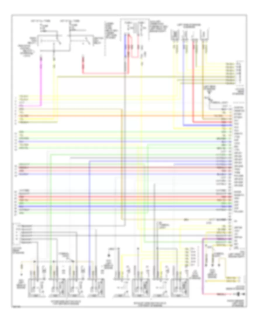
1.3L Hybrid, Engine Controls Wiring Diagram (5 of 5) for Honda Insight EX 2011
List of elements for 1.3L Hybrid, Engine Controls Wiring Diagram (5 of 5) for Honda Insight EX 2011:
- (left rear of engine) g101
- (left side of engine) injectors
- (thermal joint) s1
- 15a
- Afs+
- Afs-
- Afshtc
- Auxiliary under-hood fuse/relay box (left front of engine compt)
- B24
- C103
- Ckp
- Cmp
- Etcsm+
- Etcsm-
- Exhaust side ignition coils (top right of engine)
- From etcs control relay (diagram a 4 of 5)
- Fuse 1
- Fuse 15a
- Fuse 2
- Fuse 20a
- G101 (left rear of engine)
- Hot at all times
- Icm
- Ig1
- Ig1etcs
- Ignition coil relay
- Igpls1e
- Igpls1i
- Igpls2e
- Igpls2i
- Igpls31
- Igpls3e
- Igpls4e
- Igpls4i
- Igrtn2i
- Igrtne
- Inj1
- Inj2
- Inj3
- Inj4
- Intake side ignition coils (top center of engine)
- J/c c104 (rear of engine)
- J/c c105 (rear of engine)
- Knock sensor (left side of engine)
- Lg1
- Lg2
- Map
- Pcm (left front of engine compt)
- Pgm-fi main relay 1
- Pgmetcs
- Poilcsa
- Poilcsb
- Red
- S2 (thermal joint)
- Sg1
- Sg3
- Sho2s
- So2shtc
- Tpsa
- Tpsb
- Under- dash fuse/ relay box (under left side of dash)
- Vcc1
- Vcc3
- Vts1
- Vts2
1.3L Hybrid, IMA Wiring Diagram (1 of 3) for Honda Insight EX 2011
List of elements for 1.3L Hybrid, IMA Wiring Diagram (1 of 3) for Honda Insight EX 2011:
- (or pnk)
- (rear of engine) ima motor rotor position sensor
- 125a
- A10
- A11
- A12
- A13
- A14
- A15
- A16
- A17
- A18
- A19
- A20
- A21
- A22
- A23
- A24
- A25
- A26
- A27
- A28
- A29
- A30
- A31
- B10
- B11
- B12
- B13
- B14
- B15
- B16
- B17
- B18
- B19
- B20
- B21
- B22
- B23
- B24
- Battery current sensor
- Battery module
- Battery module fuse
- Battery module switch
- Battery module temperature sensor 1
- Battery module temperature sensor 2
- Battery module temperature sensor 3
- Bus bar
- Bypass contractor
- Bypass resistor
- C102
- C305
- C603
- C701
- C702
- Canh
- Canl
- Cnt
- Cntpg
- Computer data lines system
- Contractor connector (right side of ipu)
- Fanctl
- G101 (left rear of engine)
- G702 (left side of cargo area)
- G901 (under ipu lid)
- High voltage contractor
- Ig1
- Iga
- Ighld
- Ighld2
- Imacanh
- Imacanl
- Isoc
- Isocf
- J/c c104 (rear of engine)
- J/c c703 (under ipu lid)
- Junction board
- Junction board connector (junction board connector)
- Mcm (under ipu lid)
- Nfan
- Pg1
- Pnk
- Pre
- Red
- Scidm
- Sgisoc
- Sgtb
- Tbatt1
- Tbatt2
- Tbatt3
- Vbu
- Vccisoc
1.3L Hybrid, IMA Wiring Diagram (2 of 3) for Honda Insight EX 2011
List of elements for 1.3L Hybrid, IMA Wiring Diagram (2 of 3) for Honda Insight EX 2011:
- +b backup
- A13
- A38
- A39
- Auto stop indicator
- B17
- Bkswnc
- Bus bar
- C37
- C603
- C701
- C702
- Charge/assist gauge
- Charging system indicator
- Computer data lines system
- Control circuits
- Engine controls system
- F-can transceiver
- Fan ctrl
- Fuse 10a
- Fuse 15a
- Fuse 7.5a
- G501 (left side of dash)
- G701 (rear of cargo area)
- G702 (left side of cargo area)
- G901 (under ipu lid)
- Gauge control module
- Ground
- Hot at all times
- Hot in on or start
- Idle stop switch (under left side of dash)
- Ig1
- Ig1 meter
- Ignition
- Ima system indicator
- Imacanh
- Imacanl
- Interior lights system
- Ipu module fan (right rear of cargo area)
- J/c c703 (under ipu lid)
- Micu
- Multi-information display (mid) unit
- Pcm (left front of engine compt)
- Pnk
- Power distribution system
- Red
- S6 (thermal joint)
- S8 (thermal joint)
- Under-dash fuse/relay box (under left end of dash)
1.3L Hybrid, IMA Wiring Diagram (3 of 3) for Honda Insight EX 2011
List of elements for 1.3L Hybrid, IMA Wiring Diagram (3 of 3) for Honda Insight EX 2011:
- (left side of cargo area)
- (under ipu lid)
- (under ipu lid) g901
- (under ipu lid) j/c c703
- Battery
- Battery terminal fuse box (top of battery)
- Bus bar
- C10
- C11
- C12
- C13
- C14
- C15
- C16
- C17
- C18
- C19
- C20
- C21
- C22
- C49
- C603
- C701
- Dc-dc converter
- E10
- E11
- E12
- E13
- E14
- E15
- E16
- E17
- E18
- E19
- E20
- E21
- E22
- E23
- E24
- E25
- E26
- E27
- E28
- E29
- E30
- E31
- Fuse 100a
- Fuse 10a
- G5 (under ipu lid)
- G702 (left side of cargo area)
- G901 (under ipu lid)
- Gnd
- Ground
- Hi volt
- High voltage
- Hot at all times
- Hot in on or start
- Ignition
- Ima motor rotor
- Input
- Ipu serial sig
- Ipua
- Iuph
- Ivph
- Iwph
- Mcm (under ipu lid)
- Mcm relay 1 (under ipu lid)
- Mcm relay 2 (under ipu lid)
- Mpi module (under ipu lid)
- Nca
- Output
- Phase motor current sensor (under ipu lid)
- Pnk
- Red
- Sgiu
- Sgiv
- Sgiw
- T11
- T12
- T13
- T14
- T15
- T16
- T17
- U phase
- U phase hi side
- U phase lo side
- U phase motor current sensor
- Under-dash fuse/relay box (under left end of dash)
- V phase
- V phase hi side
- V phase lo side
- V phase motor current sensor
- Vcciu
- Vcciv
- Vcciw
- Vhb1
- Vhb2
- Vhb3
- Vhb4
- Vhb5
- Vhb6
- Vhb7
- Vhb8
- Vhbo
- W phase
- W phase hi side
- W phase lo side
- W phase motor current sensor