ENGINE PERFORMANCE
2.2L
2.2L, Engine Performance Wiring Diagrams (1 of 2) for Honda Odyssey EX 1995

List of elements for 2.2L, Engine Performance Wiring Diagrams (1 of 2) for Honda Odyssey EX 1995:
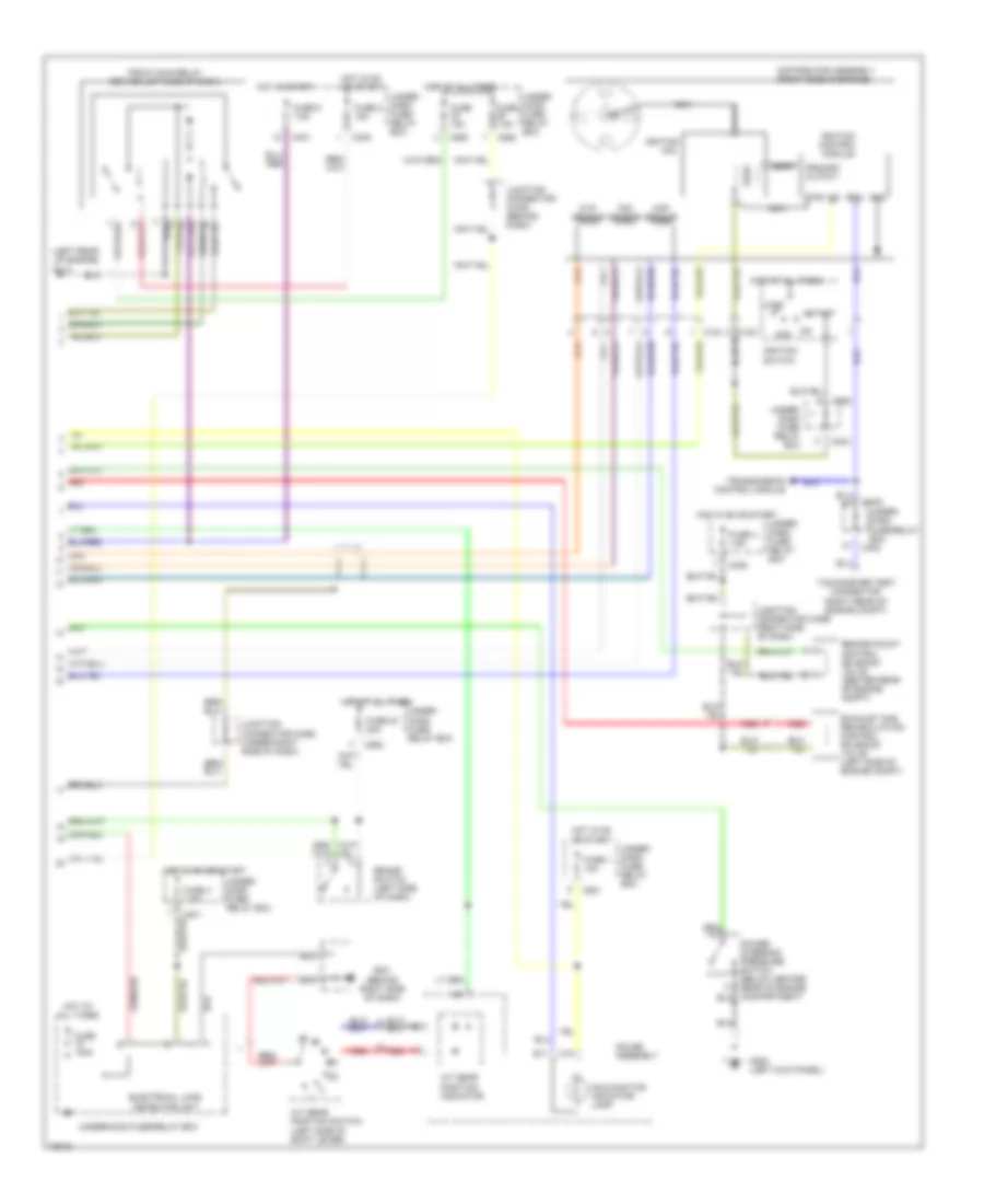
2.2L, Engine Performance Wiring Diagrams (2 of 2) for Honda Odyssey EX 1995
List of elements for 2.2L, Engine Performance Wiring Diagrams (2 of 2) for Honda Odyssey EX 1995: