POWER DISTRIBUTION
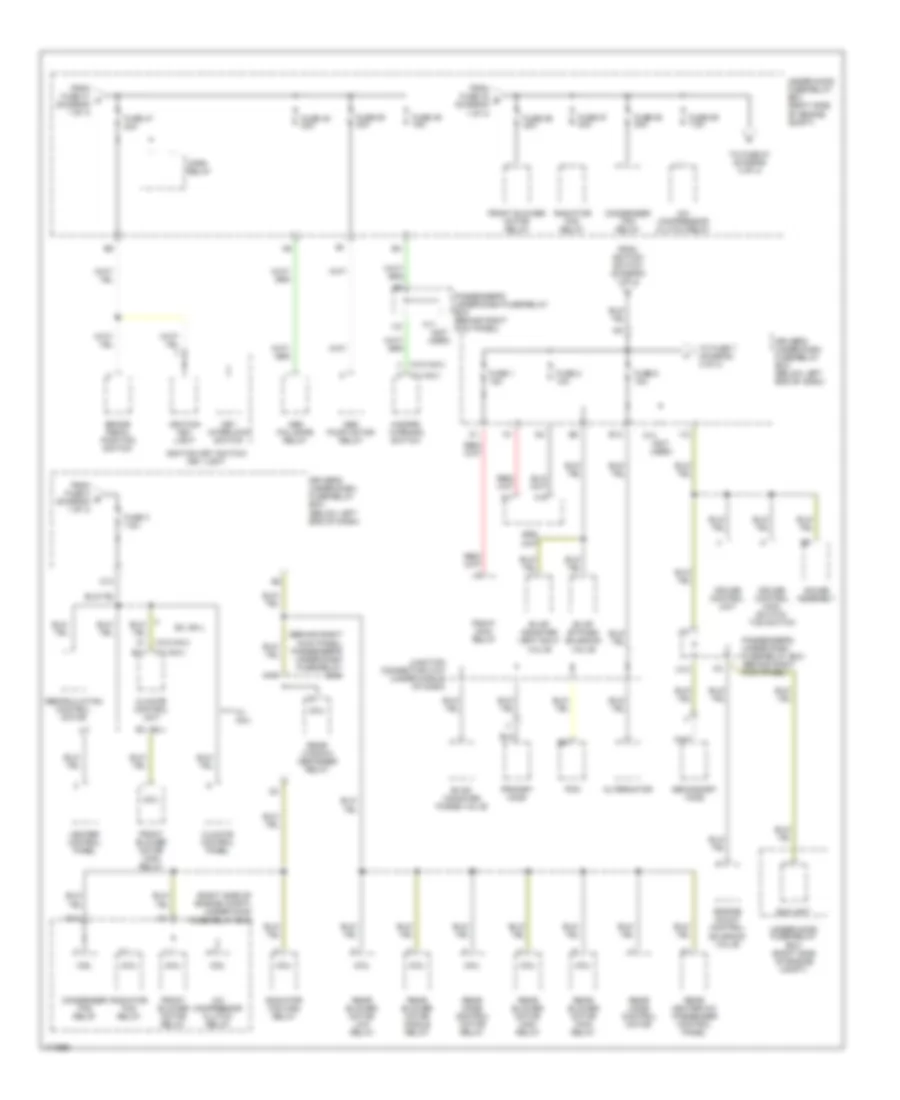
Power Distribution Wiring Diagram (1 of 4) for Honda Odyssey LX 2003

List of elements for Power Distribution Wiring Diagram (1 of 4) for Honda Odyssey LX 2003:
- (not used)
- A10
- A13
- A17
- Abs/tcs control unit
- Acc
- Alternator
- Audio unit
- Battery
- Canada
- Data link connector
- Driver's under-dash fuse/relay box (below left end of dash)
- Drl unit (canada)
- Dvd player unit
- E16
- Eld unit
- Ex, ex-l
- Ex-l
- Fuse 4 7.5a
- Fuse 41 120a
- Fuse 42 50a
- Fuse 46 15a
- Fuse 5 7.5a (canada)
- Fuse 52 30a
- Fuse 53 30a
- Fuse 71 20a
- Fuse 78 20a
- Fuse 79 20a
- Fuse 80 40a
- Fuse 81 30a
- Fusible link
- G17
- Ignition switch
- Left power sliding door control unit
- Lock
- O15
- Option connector
- Passenger's under-dash fuse/relay box (behind right kick panel)
- Pgm-fi main relay
- Power mirror switch
- Power window control unit
- Q14
- Rear blower motor
- Rear controller & screen
- Rear window defogger relay
- Red
- Right power sliding door control unit
- Seat heater relay
- Start
- Starter
- Starter cut relay
- Starter solenoid
- T option connector
- T101
- To cigarette lighter in-line fuse (diagram 3 of 4)
- To fuse 3 (diagram 2 of 4)
- To fuse 47 (diagram 2 of 4)
- To fuse 56 (diagram 2 of 4)
- To fuse 6 (diagram 2 of 4)
- To fuse 8 (diagram 3 of 4)
- Under-hood fuse/relay box (right side of engine compt)
- Under-hood sub-fuse box
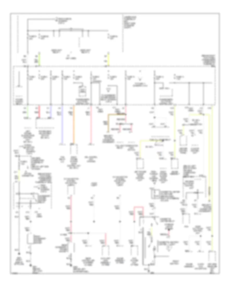
Power Distribution Wiring Diagram (2 of 4) for Honda Odyssey LX 2003
List of elements for Power Distribution Wiring Diagram (2 of 4) for Honda Odyssey LX 2003:
- (behind right kick panel) passenger's under-dash fuse/relay box
- (not used)
- (right side of engine compt) under-hood fuse/relay box
- (w/ nav)
- (w/o nav)
- A/c compressor clutch relay
- A17
- A18
- Abs fail-safe relay
- Abs pump motor relay
- Alternator
- B13
- Brake pedal position switch
- C10
- Climate control panel
- Climate control unit
- Coil
- Condenser fan relay
- Cruise control main switch/ tcs switch
- Cruise control unit
- D15
- Driver's under-dash fuse/relay box (below left end of dash)
- E13
- Eld unit
- Engine mount control solenoid valve
- Evap bypass solenoid valve
- Evap canister purge valve
- Evap canister vent shut valve
- Ex, ex-l
- From fuse 4 e (diagram 1 of 4)
- From fuse 41 a (diagram 1 of 4)
- From fuse 42 b (diagram 1 of 4)
- From ignition switch (diagram 1 of 4)
- Front blower motor high relay
- Front blower motor relay
- Fuse 1 15a
- Fuse 2 10a
- Fuse 3 7.5a
- Fuse 47 20a
- Fuse 48 20a
- Fuse 49 15a
- Fuse 50 30a
- Fuse 56 40a
- Fuse 57 30a
- Fuse 58 30a
- Fuse 59 7.5a
- Fuse 6 15a
- Gauge assembly
- Hazard warning switch
- Heater control panel
- Horn relay
- I12
- I15
- Ignition key light
- Ignition key switch/ key light
- Junction connector c107 (under middle of dash)
- K11 (not used)
- K15
- Key interlock switch
- O13
- O14
- Passenger's under-dash fuse/relay box (behind right kick panel)
- Pcm
- Pgm-fi main relay
- Primary ho2s
- Radiator fan main relay
- Radiator fan relay
- Rear blower motor high relay
- Rear blower motor low relay
- Rear blower motor main relay
- Rear blower motor middle relay
- Rear heater-a/c passenger control panel
- Rear mode control motor
- Rear mode control motor relay
- Rear window defogger relay
- Recirculation control motor
- Secondary ho2s
- Srs unit
- To fuse 51 (diagram 3 of 4)
- To fuse 7 (diagram 4 of 4)
- Under-hood fuse/relay box (right side of engine compt)
- W/ nav
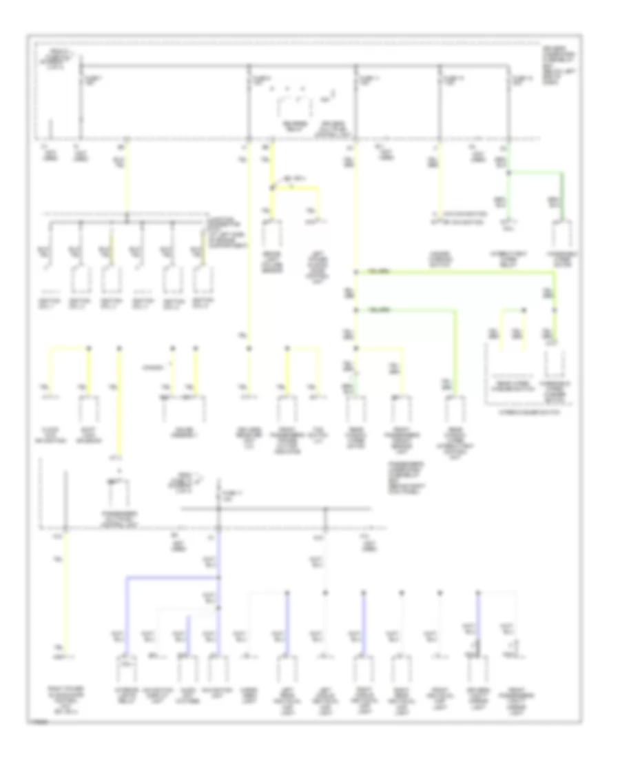
Power Distribution Wiring Diagram (3 of 4) for Honda Odyssey LX 2003
List of elements for Power Distribution Wiring Diagram (3 of 4) for Honda Odyssey LX 2003:
- (behind right kick panel) passenger's under-dash fuse/relay box
- (below left end of dash) driver's under-dash fuse/ relay box
- (not used)
- (w/ navigation system) navigation display unit
- (w/ navigation system) navigation unit
- 15a
- 20a
- 40a
- A11
- A12
- A14
- A23
- A24
- A25
- Accessory power socket relay
- Ashtray light
- Audio unit
- Auxiliary jack assembly (w/ rse)
- B20
- B21
- C15
- Cigarette lighter
- Cigarette lighter in-line fuse (behind dash, right of steering column)
- Cigarette lighter relay
- Climate control unit
- Clock (w/o navigation)
- Combination light switch
- Door multiplex control unit
- Driver's multiplex control unit
- Driver's under-dash fuse/relay box (below left end of dash)
- Drl control unit (canada)
- Dvd player unit (w/ rse)
- Ex, ex-l
- Ex, ex-l w/o navigation
- From fuse 59 (diagram 2 of 4)
- From fuse 9 (diagram 3 of 4)
- From fusible link (diagram 1 of 4)
- From ignition switch (diagram 1 of 4)
- Front accessory power socket
- Front ashtray
- Fuel fill door relay
- Fuse 1
- Fuse 10 15a
- Fuse 12 20a
- Fuse 13 7.5a
- Fuse 2 20a
- Fuse 3 10a
- Fuse 4 20a
- Fuse 5 20a
- Fuse 51
- Fuse 54 40a
- Fuse 55 40a
- Fuse 6 10a (canada)
- Fuse 8 7.5a
- Fuse 9 15a
- G501 (behind left kick panel)
- G52
- G552 (behind left quarterpanel)
- G581 (right side of "b" pillar)
- Gauge assembly
- Gauge assembly (w/ rse)
- H11
- H13
- H15
- H16
- Headlight relay 1
- Headlight relay 2
- Heater control panel
- I18
- Interior lights system
- J12
- J16
- Keyless receiver unit (ex, ex-l)
- Left power sliding door control unit
- Left power sliding door control unit (ex, ex-l)
- O11
- O19
- Option connector
- Passenger's multiplex control unit
- Pcm
- Power seat adjustment switch (ex, ex-l)
- Power window relay
- Rear accessory power socket
- Rear controller & screen (w/ rse)
- Red
- Right power sliding door control unit
- Right power sliding door control unit (ex, ex-l)
- Security system connector (accessory)
- Taillight relay
- Tcs relay (lx)
- To accessory power socket relay (diagram 3 of 4)
- To fuse 11 (diagram 4 of 4)
- Under-hood fuse/relay box (right side of engine compt)
- W/ rse
Power Distribution Wiring Diagram (4 of 4) for Honda Odyssey LX 2003
List of elements for Power Distribution Wiring Diagram (4 of 4) for Honda Odyssey LX 2003:
- (not used)
- (w/ navigation)
- (w/o navigation)
- A10
- A13
- A16
- A19
- A22
- A24
- Audio unit (w/o rse)
- B11
- B15
- Brake light failure sensor
- Canada
- Cargo area light
- Clock (w/o navigation)
- Coil
- Driver's multiplex control unit
- Driver's under-dash fuse/relay box (below left end of dash)
- Driver's vanity mirror light
- E11
- Ex, ex-l
- F10
- From fuse 10 k (diagram 3 of 4)
- From fuse 6 j (diagram 2 of 4)
- Front individual map light
- Front passenger's air bag cut-off indicator
- Front passenger's vanity mirror light
- Front passenger's weight sensor unit
- Fuse 10 7.5a
- Fuse 11 10a
- Fuse 12 30a
- Fuse 7 15a
- Fuse 9 10a
- Gauge assembly
- Hazard warning switch
- Ignition coil 1
- Ignition coil 2
- Ignition coil 3
- Ignition coil 4
- Ignition coil 5
- Ignition coil 6
- Interior lights relay
- Intermittent wiper relay
- Junction connector c104 (at left side of engine compartment)
- Keyless receiver unit (lx)
- Left middle individual map light
- Left power sliding door control unit
- Left rear individual map light
- Navigation display unit
- Navigation unit
- Nca
- Passenger's multiplex control unit
- Passenger's under-dash fuse/relay box (behind right kick panel)
- Rear window wiper intermittent control unit
- Rear window wiper motor
- Rear wiper/ washer switch
- Reverse relay
- Right middle individual map light
- Right power sliding door control unit (ex, ex-l)
- Right rear individual map light
- Shift lock solenoid
- Tcs switch (lx)
- Windshield wiper motor
- Windshield wiper/ washer switch
- Wiper/washer switch