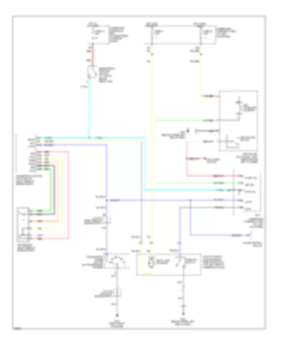
SHIFT INTERLOCK
Shift Interlock Wiring Diagram for Honda Ridgeline RTL 2011
List of elements for Shift Interlock Wiring Diagram for Honda Ridgeline RTL 2011:
- (at left kick panel)
- A16
- A18
- A19
- A24
- A25
- A26
- A27
- Anti-theft system
- App sensor (right rear of engine compt)
- Apsa
- Apsb
- Atp-p
- Bksw
- Brake pedal position switch (at top of brake pedal arm)
- D3 switch/shift lock solenoid/ park pin switch (top left side of steering column)
- Fuse 13 20a
- Fuse 21 7.5a
- Fuse 32 7.5a
- G101 (right front of engine)
- G401 (behind upper left end of dash)
- Gauge control module
- Hot at all times
- Hot in acc or on
- Hot in on or start
- Ig key sw
- Ignition key switch
- Ignition key switch/key light (near ignition key cylinder)
- J/c c101 (right rear of engine compt)
- J/c c104 (middle of engine compt)
- Key interlock solenoid
- Key sol
- Micu
- N26
- N36
- P-pin
- P13
- P15
- P16
- Park pin switch
- Powertrain control (pcm) module (right rear of engine compt)
- Red
- Sg3
- Sg4
- Shift lock solenoid
- Sls
- Stop sw
- Transmission range switch (on transmission housing)
- Under-dash fuse/relay box
- Under-dash fuse/relay box (at left kick panel)
- Under-hood fuse/relay box (at right rear of engine compt)
- Vcc3
- Vcc4
- X34
 English