SUPPLEMENTAL RESTRAINTS
Supplemental Restraints Wiring Diagram (1 of 3) for Honda Crosstour EX 2012

List of elements for Supplemental Restraints Wiring Diagram (1 of 3) for Honda Crosstour EX 2012:
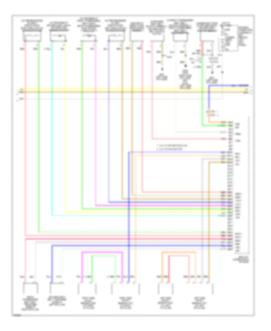
Supplemental Restraints Wiring Diagram (2 of 3) for Honda Crosstour EX 2012
List of elements for Supplemental Restraints Wiring Diagram (2 of 3) for Honda Crosstour EX 2012:
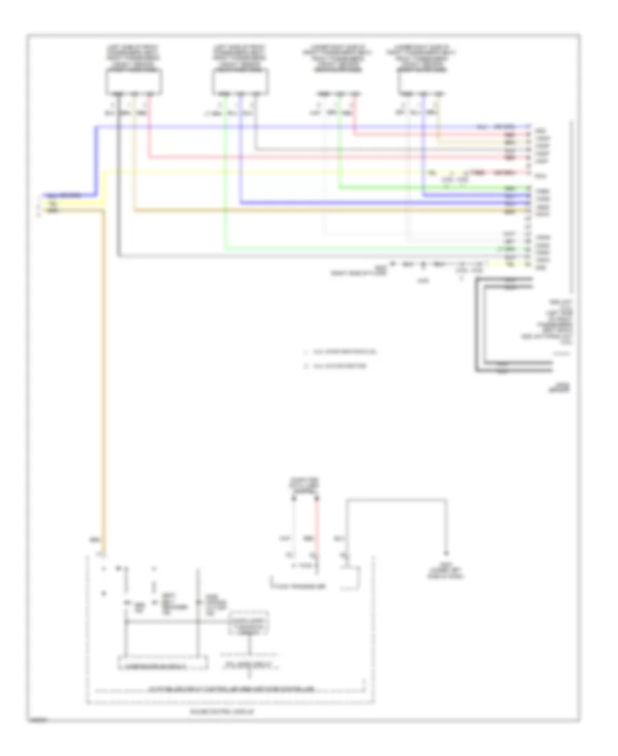
Supplemental Restraints Wiring Diagram (3 of 3) for Honda Crosstour EX 2012
List of elements for Supplemental Restraints Wiring Diagram (3 of 3) for Honda Crosstour EX 2012: