SUPPLEMENTAL RESTRAINTS
Supplemental Restraint Wiring Diagram for Honda Odyssey EX 1997
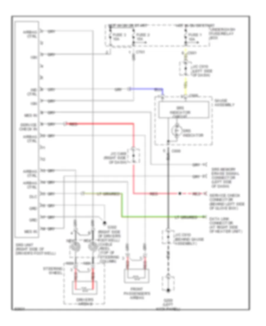
List of elements for Supplemental Restraint Wiring Diagram for Honda Odyssey EX 1997:
- (right side of driver's footwell) cable reel (top of steering column)
- Airbag ctrl
- C601
- C606
- C701
- Data link connector (at right side of heater unit)
- Dlc
- Driver's airbag
- Front passenger's airbag
- Fuse 1 10a
- Fuse 2 15a
- Fuse 3 10a
- G200 (left kick panel)
- G302
- Gauge assembly
- Grd
- Hot in on or start
- Ign
- Ind ctrl
- J/c c469 (right side of dash)
- J/c c610 (behind gauge assembly)
- J/c c610 (left side of dash)
- Mes in
- Nca
- Red
- Service check connector (behind left side of glove box)
- Service check in
- Srs indicator
- Srs indicator circuit
- Srs memory erase signal connector (left side of dash)
- Srs unit (right side of driver's footwell)
- Steering wheel
- Under-dash fuse/relay box
 English