
SUPPLEMENTAL RESTRAINTS
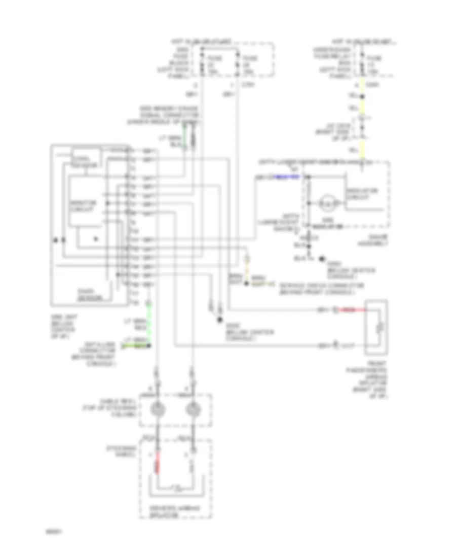
Supplemental Restraint Wiring Diagram for Honda Prelude S 1994
List of elements for Supplemental Restraint Wiring Diagram for Honda Prelude S 1994:
ANTI-LOCK BRAKESCRUISE CONTROLCOOLING FANCOMPUTER DATA LINESANTI-THEFTELECTRONIC POWER STEERINGEXTERIOR LIGHTSDEFOGGERSGROUND DISTRIBUTIONENGINE PERFORMANCEHEADLIGHTSINSTRUMENT CLUSTERAIR CONDITIONINGPOWER DOOR LOCKSHORNINTERIOR LIGHTSPOWER SEATSPOWER MIRRORSPOWER TOP/SUNROOFSHIFT INTERLOCKSPOWER DISTRIBUTIONPOWER ANTENNASTARTING/CHARGINGPOWER WINDOWSWARNING SYSTEMSTRANSMISSIONRADIOSUPPLEMENTAL RESTRAINTSWIPER/WASHER