WARNING SYSTEMS
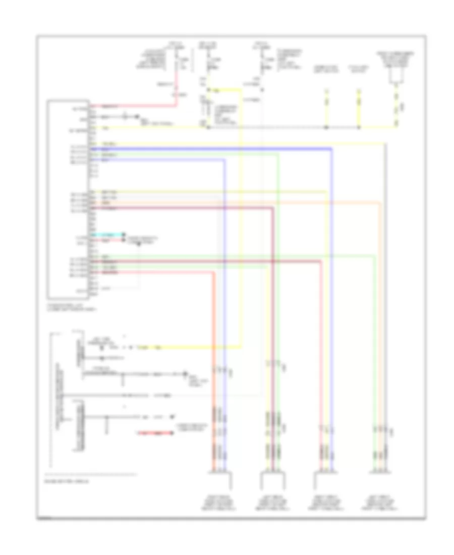
Chime Wiring Diagram for Honda Ridgeline Sport 2012

List of elements for Chime Wiring Diagram for Honda Ridgeline Sport 2012:
Tire Pressure Monitoring Wiring Diagram for Honda Ridgeline Sport 2012
List of elements for Tire Pressure Monitoring Wiring Diagram for Honda Ridgeline Sport 2012: